
Frequency shift keying modulator and applications thereof

a modulator and frequency shift technology, applied in modulation, digital transmission, pulse technique, etc., can solve the problem of little effect on the modulation properties of mixed data signals, and achieve the effect of improving the overall performance of radio transmitters, and improving the signal-to-noise ratio

Inactive Publication Date: 2009-01-22
AVAGO TECH INT SALES PTE LTD
View PDF5 Cites 1 Cited by
  • Summary
  • Abstract
  • Description
  • Claims
  • Application Information

AI Technical Summary

Benefits of technology

[0016]The various embodiments of the FSK modulator of this invention may be used in a local oscillation module and / or in an IF mixing stage of a radio transmitter. By utilizing the FSK modulator in a radio transmitter, the overall performance of the radio transmitter is enhanced because I-Q balance is easier to achieve in a lower frequency modulation circuit.

Problems solved by technology

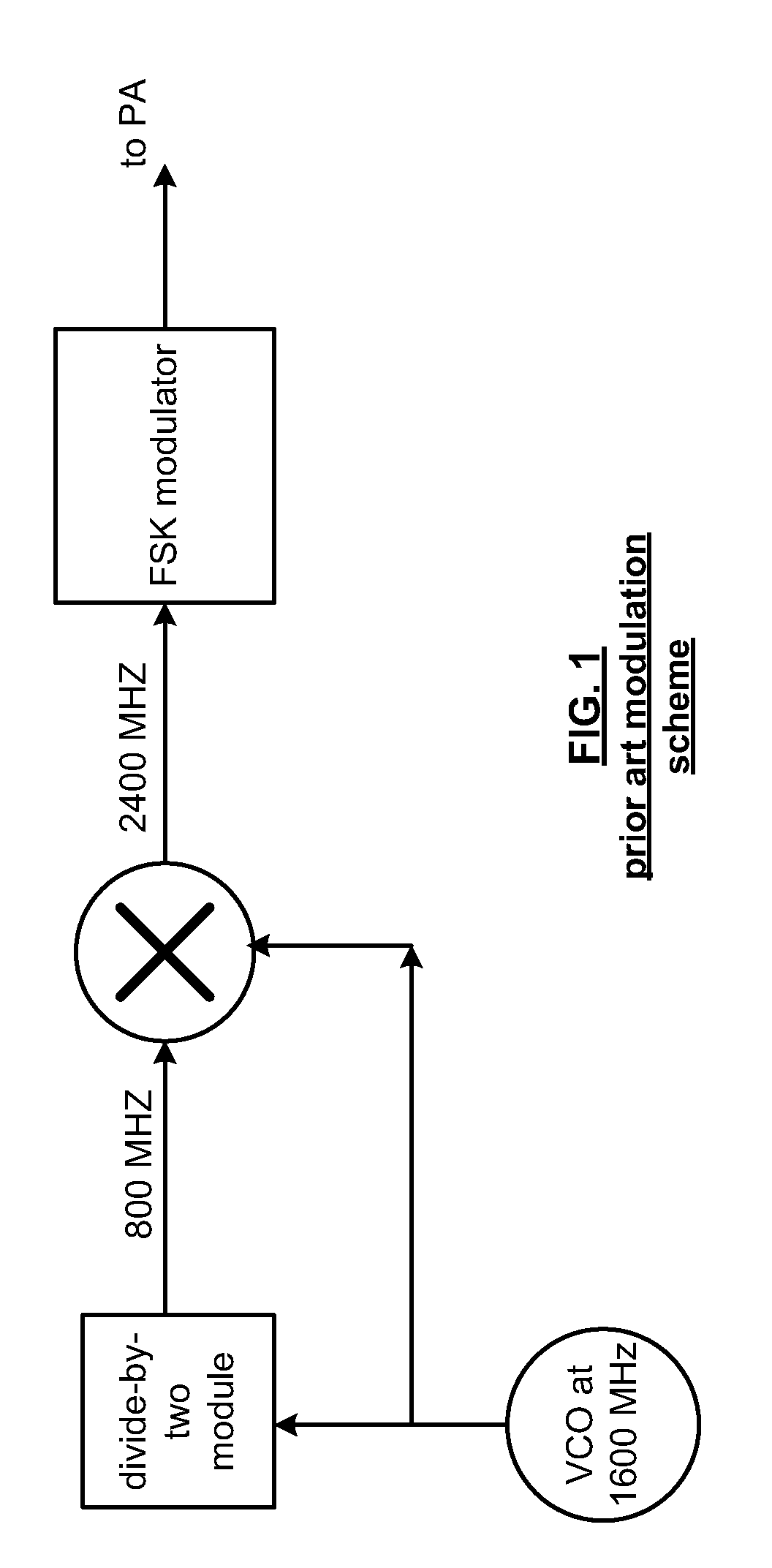
Further, any feedback of the mixed data signal back into the FSK modulator will happen at a frequency outside the frequency band of the oscillations within the image-rejection mixer, and therefore will have little effect on the modulation properties of the mixed data signal.

Method used


Image

  • Frequency shift keying modulator and applications thereof
  • Frequency shift keying modulator and applications thereof
  • Frequency shift keying modulator and applications thereof

Examples


first embodiment

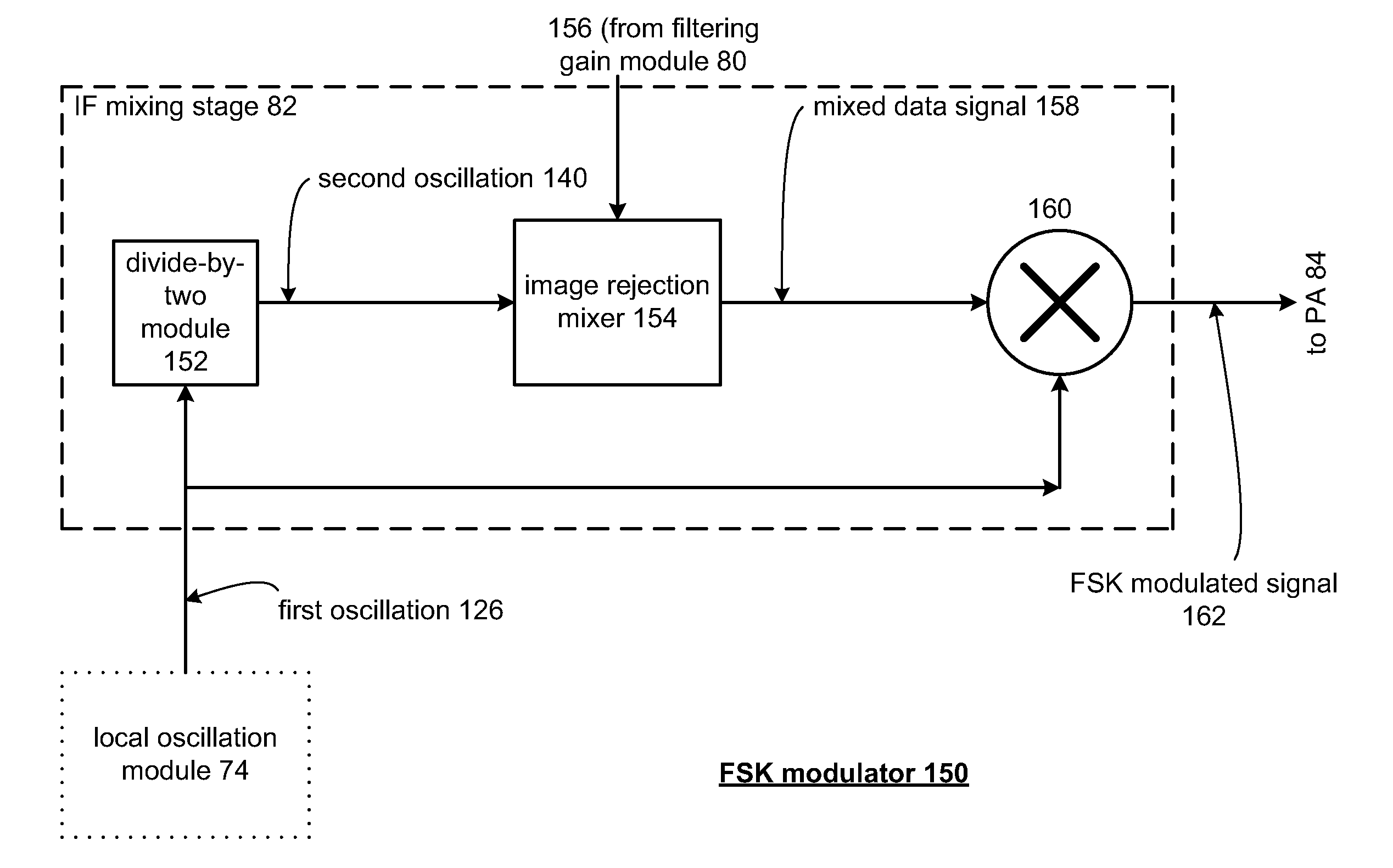
[0040]FIG. 5 is a schematic block diagram of an embodiment of FSK modulator 150 that includes a phase lock loop, a divide-by-two module, an image rejection mixer 154, and a mixing module 160. FSK modulator 150 can be incorporated within or can be IF mixing stage 82 of FIG. 3. FSK modulator 150 includes the phase-locked loop portion of local oscillation module 74 discussed with reference to FIG. 4. Local oscillation module 74 is operably coupled to generate and then provide first oscillation 126 to divider module 152 and to summing module 160. Divider module 152, which can be the same as divider module 134, comprises a divide-by-2 module. Divider module 152 is operably coupled to divide first oscillation 126 to produce second oscillation 140. Image rejection mixer 154 is operably coupled to mix second oscillation signal 140 with a low intermediate oscillation 156 to produce a mixed data signal 158. Summing module 160 is operably coupled to sum the mixed data signal 158 with the firs...

second embodiment

[0043]FIG. 6 is a schematic block diagram of an alternate embodiment of FSK modulator 150. In this embodiment, FSK modulator 150 includes the phase-locked loop portion of local oscillation module 74 discussed with reference to FIG. 4. Local oscillation module 74 is operably coupled to generate and then provide first oscillation 126 to summing module 160 and to generate and provide second oscillation 140 to image rejection mixer 154. The operation of the FSK modulator 150 of FIG. 6 is otherwise identical to that of the FSK modulator 150 illustrated in FIG. 5.

[0044]FIG. 7 is a schematic block diagram of image rejection mixer 154 of FIGS. 5 and 6. Image rejection mixer 154 comprises a first mixer 170, a first phase-shift module 172, a second phase-shift module 176, a second mixer 178 and a mixer summing module 180. First mixer 170 is operably coupled to mix the second oscillation 140 with the low intermediate oscillation 156 to produce a first mixed oscillation 174. First phase-shift ...


PUM


Abstract

An FSK modulator and applications thereof are disclosed. The FSK modulator comprises a phase-locked loop, a frequency divider module, an image rejection mixer and a summing module. The phase-locked loop is operably coupled to generate a first oscillation from a reference oscillation. The frequency divider module is operably coupled to divide the first oscillation to produce a second oscillation. The image-rejection mixer is operably coupled to mix the second oscillation with a low intermediate oscillation to produce a mixed data signal, and the summing module is operably coupled to sum the mixed data signal with the first oscillation to produce an FSK modulated signal.

Description

[0001]This patent application is claiming priority under 35 USC § 120 as a continuing patent application of co-pending patent application entitled A FREQUENCY SHIFT KEYING MODULATOR AND APPLICATIONS THEREOF, having a filing date of Apr. 30, 2004, and a Ser. No. 10 / 837,064, which claims priority under 35 USC § 120 as a continuing patent application of co-pending patent application entitled DIGITAL DEMODULATION AND APPLICATIONS THEREOF, having a filing date of Nov. 14, 2001 and a Ser. No. 09 / 993,541 (now U.S. Pat. No. 6,907,089).TECHNICAL FIELD OF THE INVENTION[0002]This invention relates generally to wireless communication systems and, more particularly, to radio frequency integrated circuits used in such wireless communication systems.BACKGROUND OF THE INVENTION[0003]Communication systems are known to support wireless and wire-lined communications between wireless and / or wire-lined communication devices. Such communication systems range from national and / or international cellular te...

Claims


Application Information

Patent Timeline
Patent Type & Authority Applications(United States)
IPC IPC(8): H04L27/12H03C3/00
CPCH04L27/12
Inventor BAKER, TOMJENSON, HENRIK T.
Owner AVAGO TECH INT SALES PTE LTD
Learn More