Network node, user equipment and methods for handling signal quality variations

A signal quality and network node technology, applied in location-based services, wireless communication, access restrictions, etc., can solve problems such as loss of line of sight to the base station, signal discarding, shading and increased penetration loss, etc., to achieve improved radio performance Effect

Pending Publication Date: 2021-12-31
TELEFON AB LM ERICSSON (PUBL)
View PDF0 Cites 1 Cited by
  • Summary
  • Abstract
  • Description
  • Claims
  • Application Information

AI Technical Summary

Problems solved by technology

However, when operating at higher frequencies in NR, such as for example above 28 GHz, shadowing and penetration losses will increase because higher frequencies
This can lead to very rapid signal drops, for example when the UE is operating in an urban environment (e.g. in a city) and loses line of sight to the base station, for example when the UE turns a corner and a building or obstacle blocks access from the UE When the direct radio path to the serving base station

Method used


Image

  • Network node, user equipment and methods for handling signal quality variations
  • Network node, user equipment and methods for handling signal quality variations
  • Network node, user equipment and methods for handling signal quality variations

Examples


Embodiment Construction

[0042] As part of developing the examples herein, the inventors have identified the issues that will be discussed first.

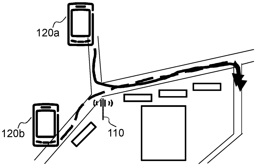
[0043] figure 1 A scenario is disclosed where the network node 110 is located in an urban area, such as for example a city center comprising a large number of buildings and obstacles. The network node 110 has a service area in which it can serve UEs. When a UE moves through an urban area, it typically follows a specific path determined by the streets of the urban area. When the UE is in the vicinity of the network node 110, the network node 110 may provide high signal quality for transmission to the UE. However, if the UE suddenly turns around a street corner, surrounding buildings may block the direct line of sight between the UE and the network node 110 . This may cause a sudden drop in signal quality for mobile UEs. figure 1 The dotted line in indicates that when served by the network node 110, and when the UE is along figure 1 Compared with the pa...


PUM


Abstract

Embodiments herein relate to a method performed by a network node (110) for handling signal quality variations for UE (120). The network node (110) predicts a future signal quality variation indicative of a path of movement for second UE (120b) being served by the network node (110). The predicting is based on historical data of previous signal quality variations for one or more first UE (120a) having been served by the network node (110). The historical data of previous signal quality variations is indicative of a path of movement of the one or more first UE (120a). The network node (110) determines to change a network configuration for the second UE (120b) based on the predicted signal quality variation. The network node (110) initiates the change of the network configuration for the second UE (120b). Embodiments herein further relate to a method performed by UE (120a, 120b) for handling signal quality variations for the UE (120a, 120b).

Description

technical field [0001] Embodiments herein relate to a network node, user equipment (UE) and methods performed therein. In particular, they relate to predicting signal quality variations of UEs in a wireless communication network. Background technique [0002] In a typical wireless communication network, a wireless device (also referred to as wireless communication device, mobile station, station (STA) and / or user equipment (UE)) communicates with a or multiple Core Network (CN) communications. The RAN covers a geographical area divided into service areas or cell areas (they may also be referred to as beams or beam groups), where each service area or cell area is served by a radio network node such as a radio access node, e.g. A Wi-Fi access point or radio base station (RBS), which in some networks may also be denoted as a NodeB, eNodeB (eNB) or, in fifth generation (5G), gNB. A service area or cell area is a geographical area where radio coverage is provided by a radio ne...

Claims


Application Information

Patent Timeline
Patent Type & Authority Applications(China)
IPC IPC(8): H04B17/318H04W4/029H04W36/24H04W72/08H04W36/14H04W36/30H04W36/32H04W40/12H04W48/18H04W72/54
CPCH04W40/12H04W4/029H04B17/318H04B17/373H04B17/336H04W40/34H04W48/06Y02D30/70H04W72/51H04W72/54H04W36/008375H04W24/08
Inventor H·赖登P·拉玛钱德拉申巍A·帕里切赫特鲁杰尼
Owner TELEFON AB LM ERICSSON (PUBL)
Why Eureka
Try Eureka