Low profile hinge with three-dimensional mechanical adjustment

Active Publication Date: 2006-10-10
GRASS AMERICA
View PDF23 Cites 37 Cited by
  • Summary
  • Abstract
  • Description
  • Claims
  • Application Information

AI Technical Summary

Benefits of technology

[0013]It is a feature and advantage of the present invention to provide a hinge with three-dimensional mechanical adjustment means which are independent of one another and do not require adjustment of the mounting screw.
[0014]Features of a hinge assembly of the present invention may be accomplished singularly, or in combination, in one or more of the embodiments of the present invention. As will be appreciated by those of ordinary skill in the art, the present invention has wide utility in a number of applications as illustrated by the variety of features and advantages discussed below.
[0015]As will be realized by those of skill in the art, many different embodiments of a hinge assembly according to the present invention are possible. Additional uses, objects, advantages, and novel features of the invention are set forth in the detailed description that follows and will become more apparent to those skilled in the art upon examination of the following or by practice of the invention.
[0016]Thus, there has been outlined, rather broadly, the more important features of the invention in order that the detailed description that follows may be better understood and in order that the present contribution to the art may be better appreciated. There are, obviously, additional features of the invention that will be described hereinafter and which will form the subject matter of the claims appended hereto. In this respect, before explaining several embodiments of the invention in detail, it is to be understood that the invention is not limited in its application to the detail

Problems solved by technology

Many of such devices include multiple adjustment components making them bulky, difficult to adjust, quick to wear, and unstable.
This is a cumbersome method of adjusting the hinge and often leads to deterioration of the wood and eventual failure of the hinge to support the weight of the door.
In another prior art hinge design,

Method used


Image

  • Low profile hinge with three-dimensional mechanical adjustment
  • Low profile hinge with three-dimensional mechanical adjustment
  • Low profile hinge with three-dimensional mechanical adjustment

Examples


Embodiment Construction

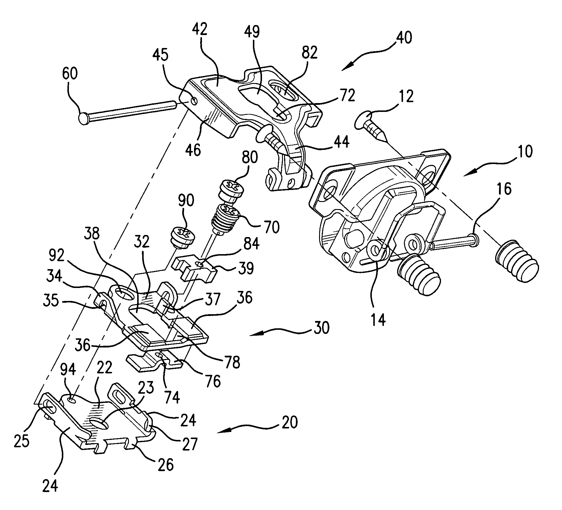
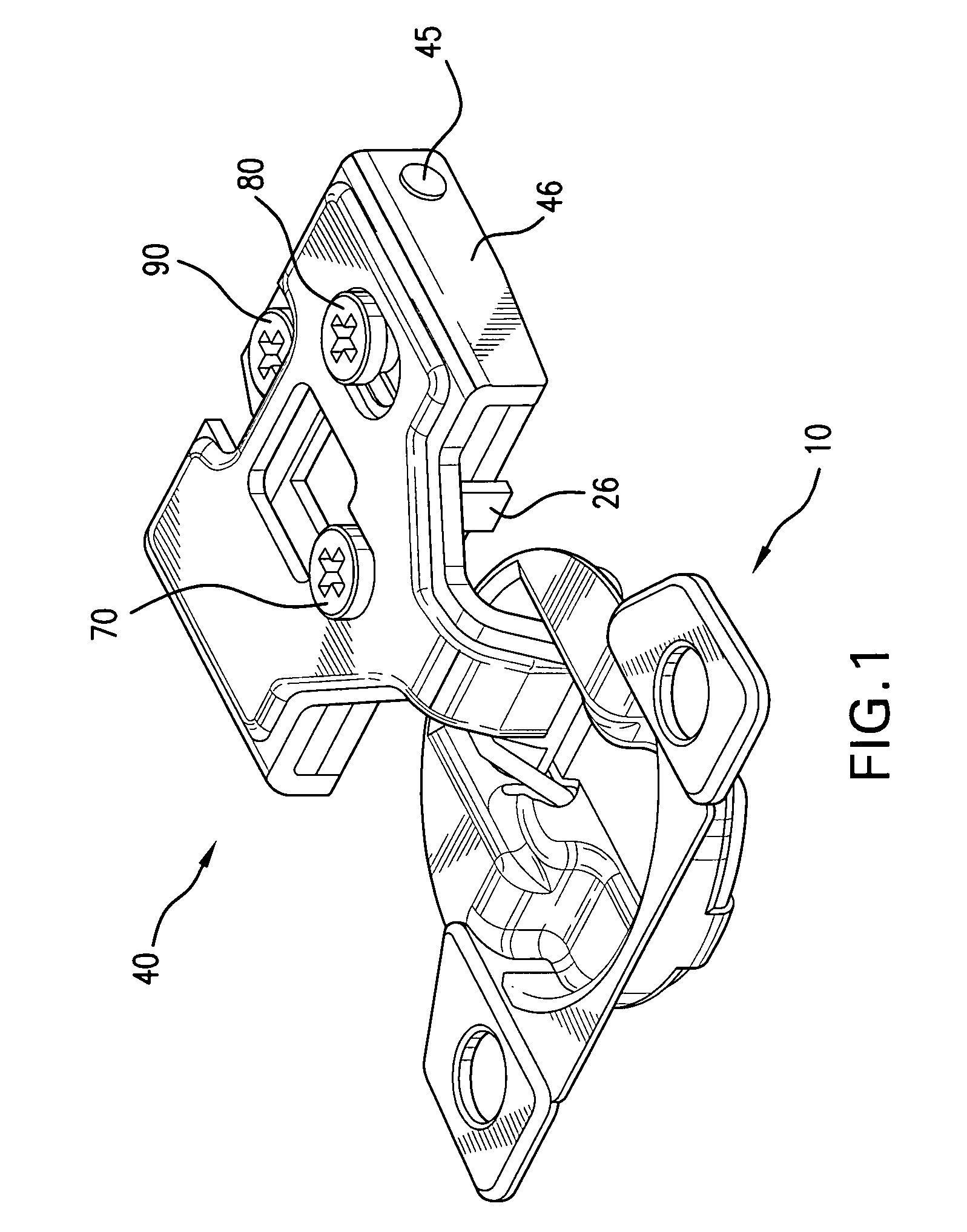
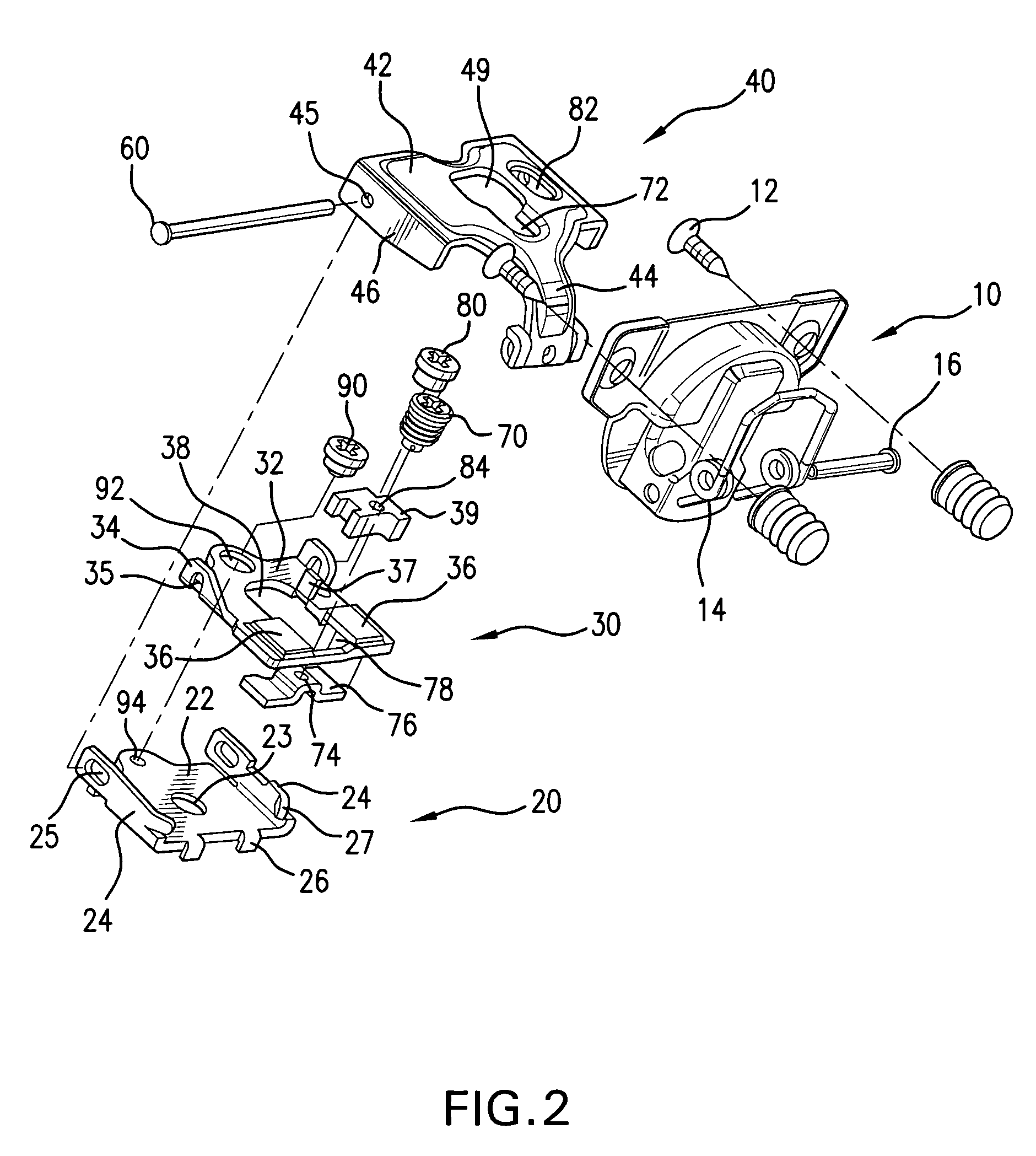
[0022]For the purposes of promoting an understanding of the invention, reference will now be made to some preferred embodiments of the present invention as illustrated in FIGS. 1–3, and specific language used to describe the same. Numerous specific details are set forth below in order to provide a thorough understanding of the present invention. However, it will be obvious to one skilled in the art, that the present invention may be practiced without some or all of these specific details. Therefore, it should be understood that no limitation of the scope of the invention is hereby intended. The terminology used herein is for the purpose of description, not limitation. Any modifications or variations in the depicted hinges, and such further applications of the principles of the invention as illustrated herein, as would normally occur to one skilled in the art, are considered to be within the spirit of this invention.

[0023]During the description of the many embodiments of the present ...


PUM


Abstract

Hinge assembly for mounting a door on a furniture frame for movement of the door between open and closed positions of the door relative to the furniture frame comprising a mounting plate adapted to be affixed to a furniture frame member an intermediate plate disposed atop of and slideably engaged to said mounting plate a top plate disposed atop of and slideably engaged to said intermediate plate and said mounting plate, and further comprising a hinge arm extending from a front portion thereof, and a guide pin extending through a rearward portion of said top plate, through a rearward portion of said intermediate plate, and through a rearward portion of said mounting plate such that said top plate is pivotable upon said guide pin. Further, the hinge assembly is adjustable such that the hinge arm can be adjusted in three dimensions relative to the mounting plate.

Description

FIELD OF THE INVENTION[0001]The present invention relates generally to hinge devices for mounting a door on a furniture article, and more particularly to adjustable hinge devices for hanging doors on cabinets or the like so that the doors can be adjusted relative to the supporting frame they are attached to.BACKGROUND OF THE INVENTION[0002]Various types of hinges for mounting a door on a furniture article such as a desk or cabinet have been used in the furniture and cabinetry industry for many years. An example of one such device is known from U.S. Pat. No. 4,716,622. Many of such devices include multiple adjustment components making them bulky, difficult to adjust, quick to wear, and unstable. Typically, one or more screws must be loosened, an adjustment made manually, and then one or more screws must be re-tightened to secure the adjustment. Accordingly, many adjustable hinges may require more than one person to accomplish the adjustment. Examples of such hinges include those desc...

Claims


Application Information

Patent Timeline
IPC IPC(8): E05D7/04
CPCE05D7/0407Y10T16/5321E05Y2900/20E05D7/0415
Inventor DOMENIG, GEORGMORGAN, JEFFERY W.
Owner GRASS AMERICA
Why Eureka
Try Eureka