Eureka AIR delivers breakthrough ideas for toughest innovation challenges, trusted by R&D personnel around the world.

Push button

a push button and button technology, applied in the field of push buttons, can solve the problems of excessive force, damage to the push button, and damage to the switch and circuit substrate,

Inactive Publication Date: 2006-10-10
TOYODA GOSEI CO LTD
View PDF6 Cites 8 Cited by
  • Summary
  • Abstract
  • Description
  • Claims
  • Application Information

AI Technical Summary

Benefits of technology

[0009]The present invention has been developed in view of such circumstances. It is therefore an object of the present invention to provide a push button, which comprises a button body and a panel body and which scarcely damages interiors such as circuit substrates and switches when the button body is pressed into the panel body too hard. Moreover, it is a further object of the present invention to provide a push button which makes the inside invisible.
[0014]The present push button comprises the button body provided with the rim, and the cylinder-shaped holder provided with the flange. The flange is brought into contact with the rim, and thereby regulates the displacement of the button body.
[0016]In the second aspect of the present invention, the present push button comprises the tapered surface, and the boss. The boss is brought into contact with the tapered surface, and thereby guides the movement of the button body or the panel body.
[0018]In the third aspect of the present invention, the rim of the button body is disposed to the presser thereof. Accordingly, it is possible to dispose the pressing surface of the presser so as to be flush with an exterior surface in the main body of the panel body. Consequently, the decorative appearance of the present push button is furthermore enhanced.
[0021]In the present push button, the button body comprises the rim, and the cylinder-shaped holder of the panel body comprises the flange. When the presser is pushed into the main body of the panel body inward, the presser displaces inside the main body inward, and the rear surface of the rim contacts with the flange. When the rim thus contacts with the flange, the button body is inhibited from displacing. Accordingly, the button body cannot be pushed into the panel body more than necessary. Consequently, no excessive forces are exerted to circuit substrates or switches which are operated by the present push button. As a result, the present push button scarcely damages circuit substrates or switches. Moreover, the rim of the button body and / or the flange of the panel body make the interiors, such circuit substrates and switches, invisible through a clearance between the button body and the panel body.

Problems solved by technology

Accordingly, there is a fear that the push button might be damaged when the operating portion is pushed in too hard.
Moreover, when the operating portion is pushed in too hard, excessive forces are applied to a switch, which is operated by the push button, and a circuit substrate, with which the switch is assembled.
Consequently, there is a problem that damages might occur in the switch and circuit substrate.
Thus, there arises another problem that the appearance of the display apparatus might degrade.

Method used


Image

  • Push button
  • Push button
  • Push button

Examples


examples

[0054]Hereinafter, the present invention will be described in detail with reference to specific examples. A few of push buttons were manufactured as examples of the present invention.

example no.1

Example No. 1

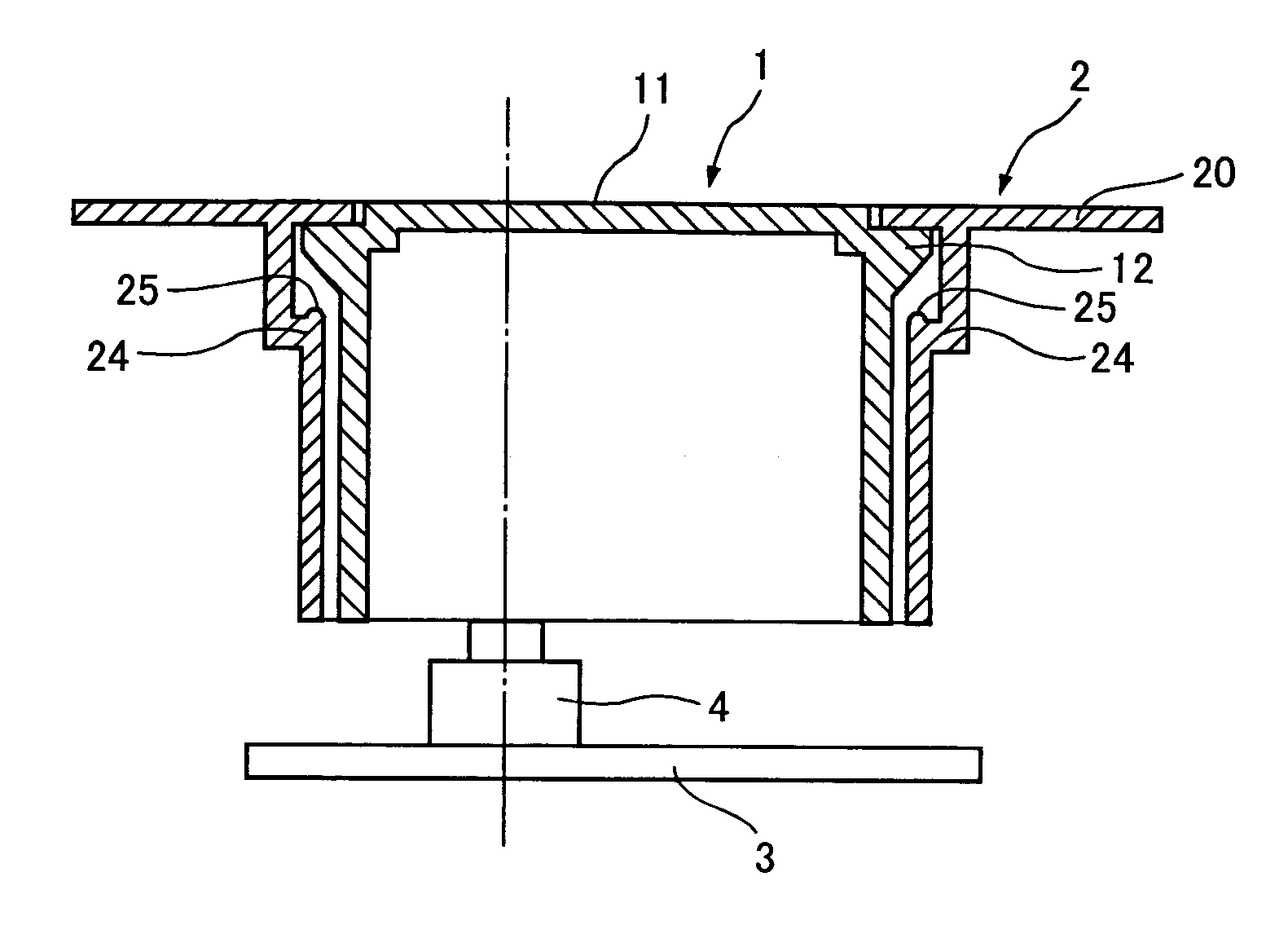
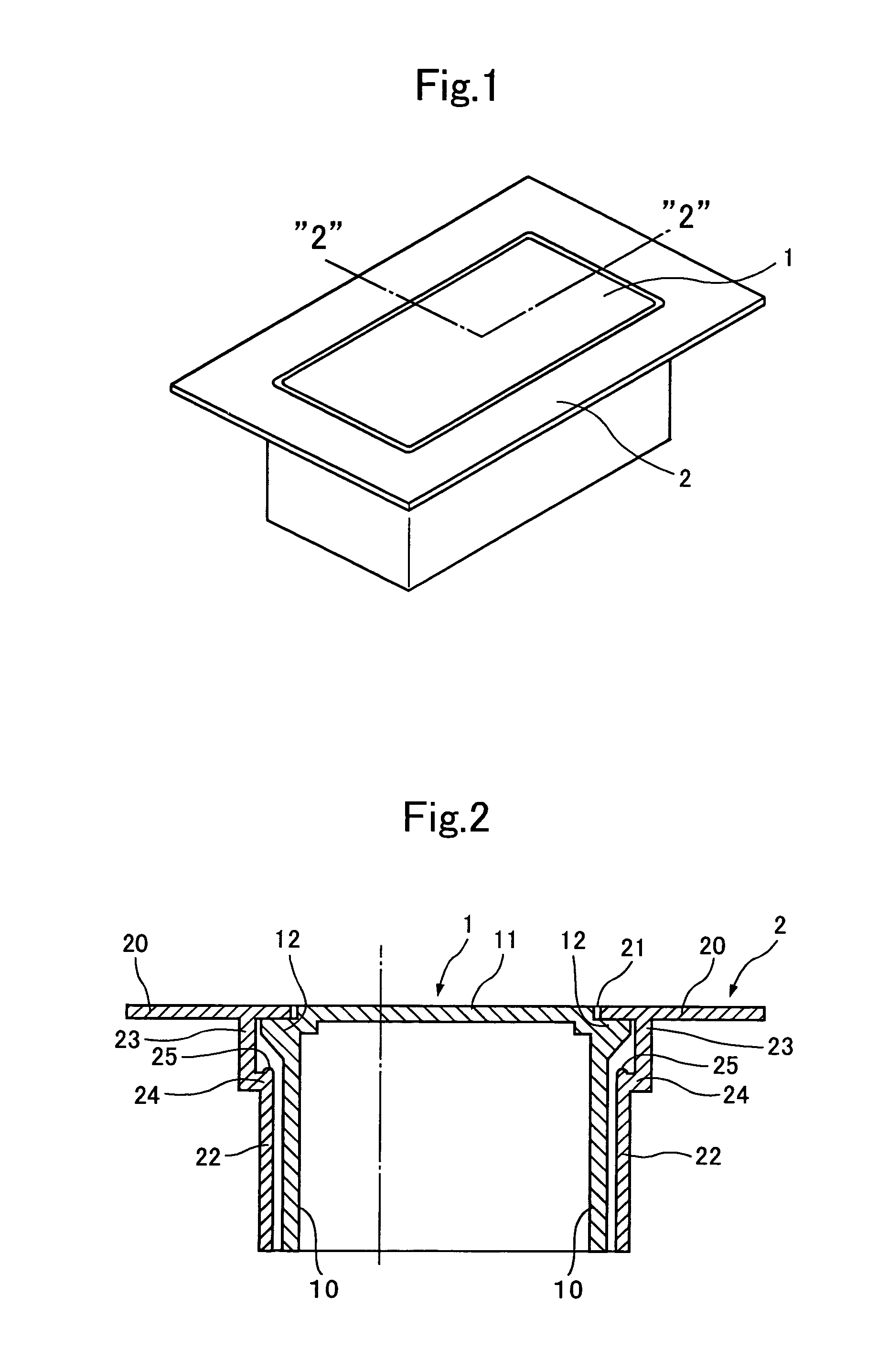
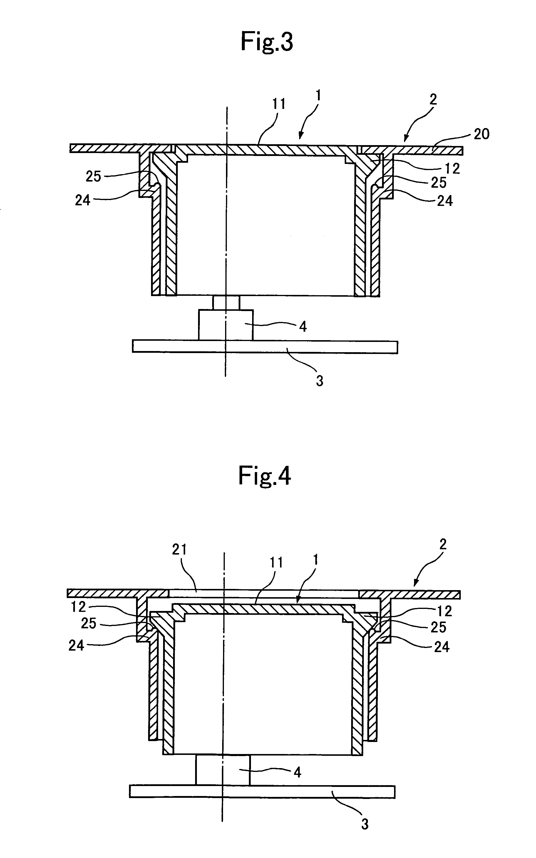
[0055]Example No. 1 of the present invention is a push button whose arrangement is illustrated in FIGS. 1 through 4. FIG. 1 illustrates a perspective view of the push button according to Example No. 1 of the present invention. FIG. 2 illustrates a cross-sectional view of the push button according to Example No. 1, taken along the chain line “2”—“2” of FIG. 1. Moreover, FIGS. 3 and 4 illustrate a cross-sectional view of the push button according to Example No. 1 in operation, respectively.

[0056]As illustrated in the drawings, the push button according to Example No. 1 comprises a button body 1, and a panel body 2.

[0057]The button body 1 comprises a cylinder 10, a presser 11, and a rim 12. The cylinder 10 is formed as a cylinder shape whose cross section is a rectangular shape substantially. The presser 11 is disposed at one of the opposite ends of the cylinder 10 (e.g., an outer opposite end), and forms a pressing surface. The rim 12 is disposed adjacent to the rear surf...

example no.2

Example No. 2

[0069]Example No. 2 of the present invention is a push button whose arrangement is illustrated in FIG. 5. FIG. 5 illustrates a cross-sectional view of the push button according to Example No. 2 of the present invention, taken similarly to FIG. 2. As shown in the drawing, the push button according to Example No. 2 has a substantially identical shape with that of the push button according to Example No. 1.

[0070]As illustrated in FIG. 5, the push button according to Example No. 2 likewise comprises a button body 1, and a panel body 2.

[0071]The button body 1 comprises a cylindrical member 13, and a pressing member 14. The cylindrical member 13 has a diametrically-reducing portion adjacent to one of the opposite ends, an outer end 13a. The pressing member 14 is fitted into the outer end 13a of the pressing member 13, is engaged with the diametrically-reducing portion of the pressing member 13, and forms a pressing surface. The cylindrical member 13 is formed in the following...


PUM


Abstract

A push button includes a button body, and a panel body. The button body includes a cylinder, a presser, and a rim. The cylinder has opposite ends, and an outer peripheral shape. The presser is disposed at one of the opposite ends of the cylinder, and forms a pressing surface. The rim protrudes beyond the outer peripheral shape of the cylinder, and has a rear surface facing the pressing surface back-to-back. The panel body includes a cylinder-shaped holder, a main body, and a flange. The cylinder-shaped holder holds the button body therein so as to enable the button body to reciprocate in an axial direction of the cylinder, and has an opening. The main body demarcates the opening of the cylinder-shaped holder. The flange protrudes radially inward, and has a leading end to be brought into contact with the rear surface of the rim.

Description

BACKGROUND OF THE INVENTION[0001]1. Field of the Invention[0002]The present invention relates to a push button. More particularly, it relates to a push button comprising a button body and a panel body wherein the inside is invisible through a clearance between the button body and the panel body when the button body is pushed into the panel body. Moreover, it relates to a push button which hardly damages interiors such as circuit substrates and switches.[0003]2. Description of the Related Art[0004]The operations of various apparatuses are controlled with switches which are disposed on and assembled with a circuit substrate. In such apparatuses, the circuit substrate is held in a case, and accordingly switches disposed on the circuit substrate are also held in the case. The switches are operated in turn with operating means, such as push buttons, disposed in the case.[0005]A push button for such an application is disclosed in Japanese Unexamined Patent Publication (KOKAI) No. 2000-306...

Claims


Application Information

Patent Timeline
Patent Type & Authority Patents(United States)
IPC IPC(8): H01H3/12H01H13/14
CPCH01H13/14H01H2221/03
Inventor KATAGIRI, KATSUHIRO
Owner TOYODA GOSEI CO LTD
Why Eureka
Eureka Blog
Learn More