Cordless power tool with tool identification circuitry

a technology of identification circuit and power tool, which is applied in the direction of portable power tools, secondary cells servicing/maintenance, safety/protection circuits, etc., can solve the problem of notifying the battery pack of any particulars of the cordless power tool

Active Publication Date: 2006-10-10
O2 MICRO INT LTD
View PDF7 Cites 156 Cited by
  • Summary
  • Abstract
  • Description
  • Claims
  • Application Information

AI Technical Summary

Problems solved by technology

However, there is no way of notifying the battery pack of any particulars of the cordless power tool.

Method used


Image

  • Cordless power tool with tool identification circuitry
  • Cordless power tool with tool identification circuitry
  • Cordless power tool with tool identification circuitry

Examples


Embodiment Construction

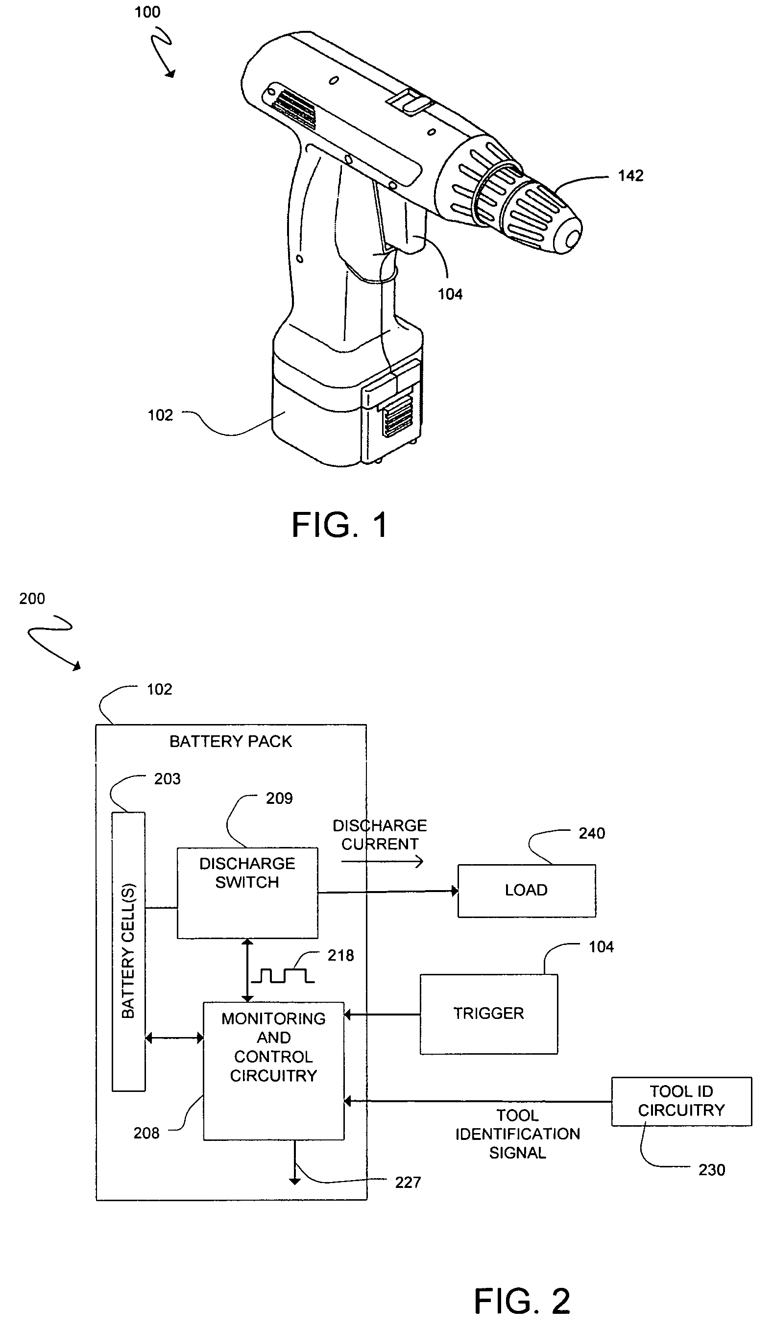
[0019]FIG. 1 is a perspective view of a cordless power tool 100. The cordless power tool 100 is illustrated as a cordless drill and may be described as such in relation to embodiments herein. However, the cordless power tool 100 may be any type of cordless power tool including, but not limited to, a cordless circular saw, a cordless reciprocating saw, a cordless sander, a cordless screwdriver, and a flashlight. The cordless power tool may include a rechargeable battery pack 102 for providing power to operate the tool 100. The rechargeable battery pack 102 may be readily removed from the cordless power tool 100 and coupled to an external battery charger for charging purposes. The cordless power tool 100 may also include a trigger 104. For the drill, a user may depress and release the trigger 104 to control the speed of the chuck 142. For other tools such as a flashlight, a user may position a trigger to control a level of illumination from the flashlight.

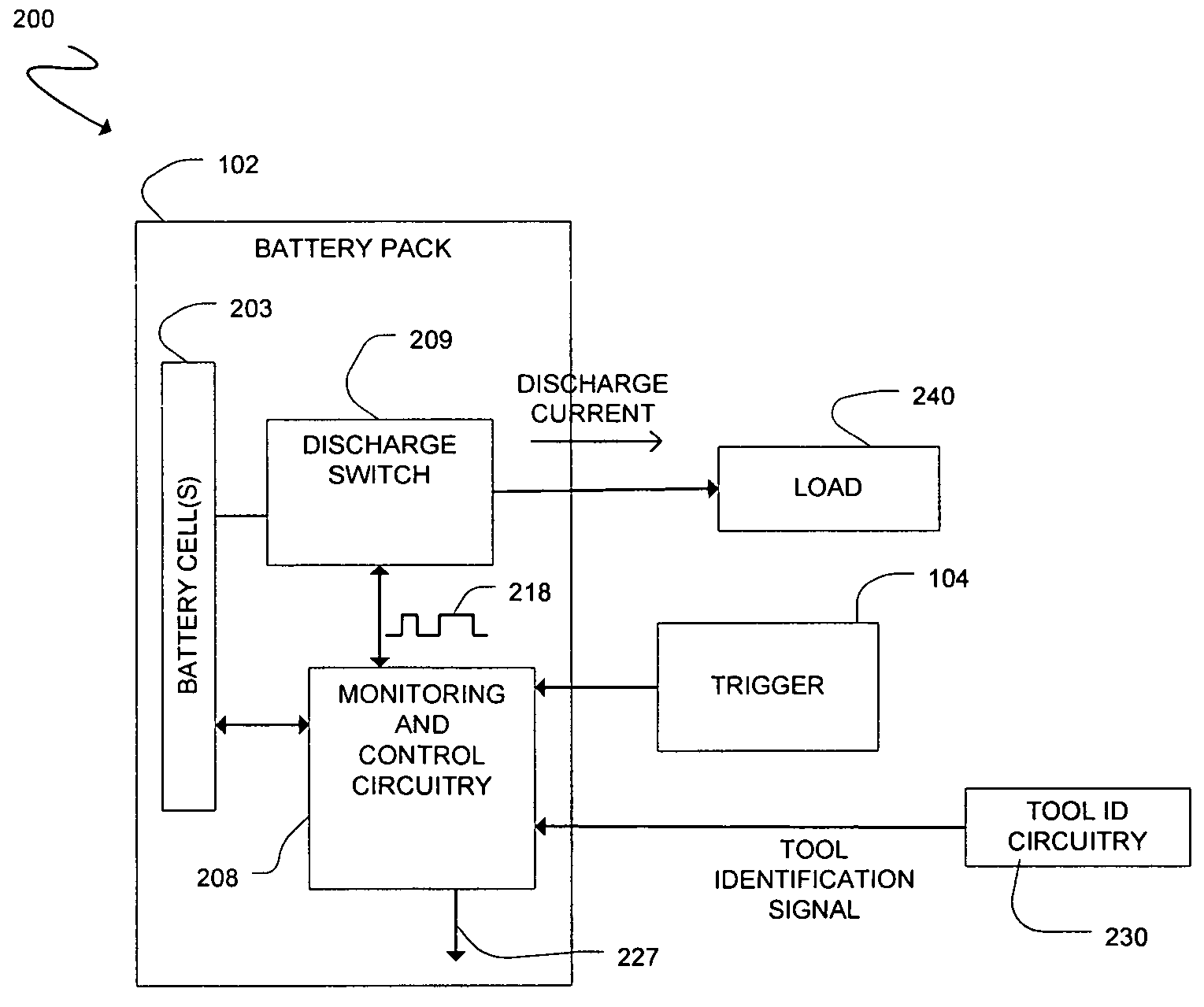
[0020]FIG. 2 is a diagram of ...


PUM

PropertyMeasurementUnit
frequencyaaaaaaaaaa
discharge currentaaaaaaaaaa
thermalaaaaaaaaaa

Abstract

A cordless power tool may include tool identification circuitry to provide a tool identification signal to a battery pack. The tool identification signal may be representative of data particular to the cordless power tool. A method may include coupling a battery pack to a cordless power tool, and providing a tool identification signal to the battery pack from the cordless power tool once the battery pack is coupled to the cordless power tool, the tool identification signal representative of data particular to the cordless power tool.

Description

CROSS REFERENCE TO RELATED APPLICATIONS[0001]This application claims the benefit of the filing date of U.S. Provisional Application Ser. No. 60 / 568,038, filed May 4, 2004, the teachings of which are incorporated herein by reference.FIELD[0002]The present disclosure relates to cordless power tools and, more particularly, to a cordless power tool with tool identification circuitry.BACKGROUND[0003]A wide variety of cordless power tools are available that may be utilized in different applications such as construction applications, fire and rescue applications, etc. Some examples of cordless power tools include, but are not limited to, cordless drills, cordless circular saws, cordless reciprocating saws, cordless sanders, cordless screwdrivers, and flashlights. Cordless power tools may utilize a rechargeable battery pack for providing power to operate the tool. The rechargeable battery pack may be readily removed from the cordless power tool and coupled to an external battery charger for...

Claims


Application Information

Patent Timeline
Patent Type & Authority Patents(United States)
IPC IPC(8): H02J7/00B25F5/00H01M10/44H02H7/18H02J7/02H02P7/28H02P7/285
CPCB25F5/00H02J7/0031H02J7/0063H02J2007/0067H02J2007/0098Y10S388/903H01M10/4257H02J7/0029Y02E60/10H02J7/007182H02J7/00308H02J7/00304
Inventor DENNING, BRUCE S.
Owner O2 MICRO INT LTD
Why Eureka
Try Eureka