
Orthotic assembly having stationary heel post and separate orthotic plate

a technology of orthotic plate and heel post, which is applied in the field of orthotic inserts, can solve the problems of modifying the shoe, affecting the comfort of the shoe, and the operation of such devices is often less than satisfactory,

Inactive Publication Date: 2006-10-24
NORTHWEST PODIATRIC LAB
View PDF14 Cites 30 Cited by
  • Summary
  • Abstract
  • Description
  • Claims
  • Application Information

AI Technical Summary

Benefits of technology

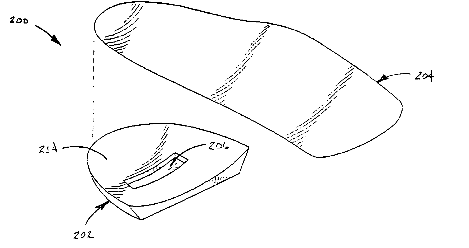
[0022](a) a post member mounted in a substantially stationary position in the shoe, the post member comprising an elongate guide slot on an upper side thereof; and (b) a thin, substantially rigid plate member for engaging the plantar surface of the wearer's foot, the plate member being substantially free from attachment to the post member and comprising a heel cup formed in a heel portion thereof, and a peg portion depending from a lower surface of the heel portion that is received in the guide slot in the post member so that the peg portion cooperates with the guide slot to control and direct movement of the plate member atop the post member.

Problems solved by technology

For several reasons, however, the operation of such devices is frequently less than satisfactory.
For example, achieving the correct pivoting motion is highly dependent on the engagement between the bottom surface of the post and the underlying insole, but the contours of most insoles tend to be irregular and vary greatly from shoe to shoe; in an effort to provide a uniform surface for the post, some practitioners have resorted to filling in the heel area of the insole to provide a more or less flat, uniform surface, but this is an expensive and time-consuming process, and also modifies the shoe so that in some instances it can no longer be used without the orthotic.
Furthermore, the rearward portion of the device must have sufficient clearance between it and the interior of the shoe to allow for the pivoting motion (or else the edge of the device will rub against the inside of the shoe), but where the heel counter of the shoe is particularly tight it may not be possible to establish this clearance, at least without having to modify the device to the point where it is ineffective or uncomfortable to wear.
Even in those instances where the heel counter is sufficiently large or loose to accommodate the device, time-consuming trimming and grinding of the device is often necessary to establish the proper motion.
Moreover, even when such devices do function as intended, the results have generally been less than ideal from a biomechanical standpoint.
Yet another problem which is inherent in conventional posted orthotic devices of the type which has been described above is that fabrication of the built-up structure is notably labor-intensive and expensive from a manufacturing perspective.
Moreover, extensive and painstaking surface preparation is often necessary in order for these adhesives to work properly, typically involving grinding or otherwise abrading one or both surfaces, applying both primary and final coats of adhesive, heating the components in an oven, and so on.
As a result, the need to fixedly mount the post to the orthotic plate adds significantly to the cost of the product.

Method used


Image

  • Orthotic assembly having stationary heel post and separate orthotic plate
  • Orthotic assembly having stationary heel post and separate orthotic plate
  • Orthotic assembly having stationary heel post and separate orthotic plate

Examples


Embodiment Construction

a. Overview

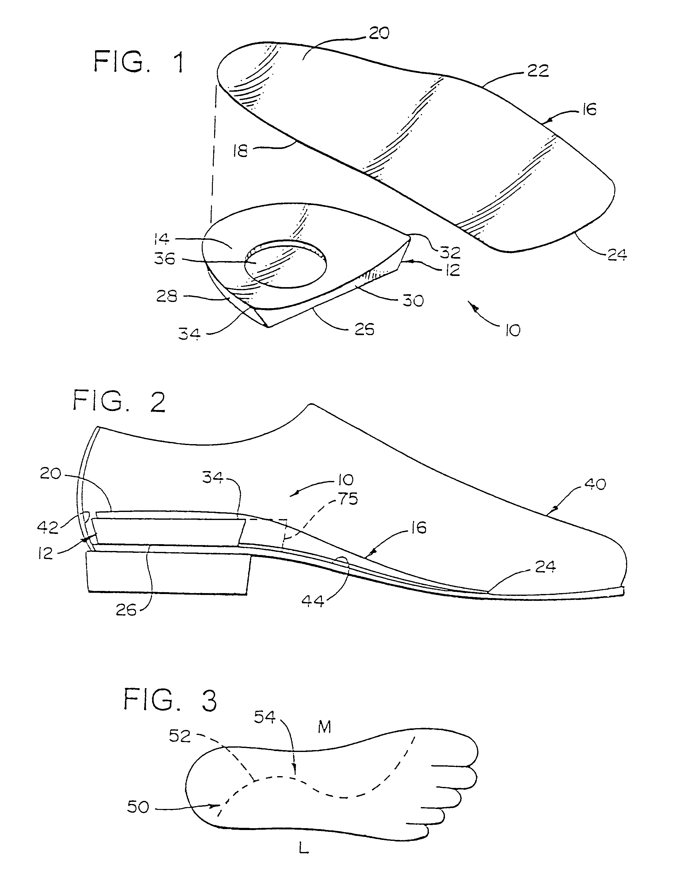
[0056]FIG. 1 shows an orthotic assembly 10 in accordance with the present invention. As can be seen, this comprises two major components, a post member 12 having a generally concave upper surface 14, and a separate plate member 16 have a generally proximal lower surface 18 which fits into and engages the concave upper surface of the post member so as to allow a pivoting or “rocking” motion between the two pieces.

[0057]The plate member includes a heel cup area 20, the upper surface of which engages the plantar surface of the wearer's rear foot, an arch portion 22 which extends beneath the arch of the foot, and a forward end 24 which engages the plantar surface of the forefoot area; in the embodiment which is illustrated, the forward edge 24 is configured to lie generally beneath the metatarsal head area of the foot, so as to lie generally flat with the frontal plane of the foot in the later phases of the gait cycle. The plate member can be formed of any suitable, generally...


PUM


Abstract

An orthotic insert assembly having a stationary heel post with a guide slot and an unattached rigid plate member with a depending peg that is received in the slot. The peg cooperates with the guide slot to control and direct a medial-to-lateral rocking movement of the plate member as the wearer's foot progresses through the gait cycle. The slot may be angled to impose a predetermined direction on the rocking movement.

Description

[0001]This application is a continuation-in-part of application Ser. No. 10 / 635,324 filed on 5 Aug. 2003 now abandoned, which is a continuation of application Ser. No. 09 / 575,830, filed May 22, 2000 issued as U.S. Pat. No. 6,601,320 B1 on 5 Aug. 2003, which is a divisional of application Ser. No. 09 / 179,249, filed Oct. 26, 1998 issued as U.S. Pat. No. 6,125,557 on 3 Oct. 2000.BACKGROUND OF THE INVENTION[0002]a. Field of the Invention[0003]The present invention relates generally to orthotic devices for use in shoes, and, more particularly, to an orthotic insert in which there is a stationary heel post and a separate plate member which is pivotable thereon so as to provide a controlled range of motion for the foot.[0004]b. Background Art[0005]Orthotic devices have long been employed with considerable success to treat conditions or otherwise enhance the functions of the human foot, whether for ordinary walking or for various forms of specialized activities, such as skiing, skating, run...

Claims


Application Information

Patent Timeline
Patent Type & Authority Patents(United States)
IPC IPC(8): A43B13/14A61F5/14
CPCA43B7/14A43B7/141A43B17/00A61F5/14
Inventor BROWN, DENNIS N.
Owner NORTHWEST PODIATRIC LAB
Learn More