Ink pad holder for self-inking stamp

a self-inking, ink pad technology, applied in stamping, printing, coatings, etc., can solve the problems of slow stamping process, messy procedure, adding too little or too much ink to the ink chamber, etc., to achieve the effect of easy reversibility and increase the quantity of ink stored in a single ink pad

Active Publication Date: 2006-10-24
SCHWAAB
View PDF7 Cites 14 Cited by
  • Summary
  • Abstract
  • Description
  • Claims
  • Application Information

AI Technical Summary

Benefits of technology

[0008]It is an object to provide a hand stamp that uses an inventive ink pad holder or tray that holds one ink pad on one side of the holder and a second ink pad on the opposite side of the holder. It is a related object to provide an ink pad that holds two different ink pads containing two different inks.
[0009]Another object is to provide an ink pad holder that is easily reversible to present the desired ink pad to the stamping member.
[0010]Still another object is to provide an ink pad holder with two ink pads separated by a non permeable dividing wall to separate the ink pads from each other.
[0011]Yet another object is to provide an ink pad holder that is divided into two compartments with an ink pad in the lower compartment and the upper compartment remaining empty for storing small objects.
[0012]The advantage of this invention is that it allows the user to select the desired ink from the two sided ink pad holder and rotate the ink pad holder so that the desired ink contacts the image forming stamp member. This invention also allows one ink to be stored in one compartment for printing and a second ink that is used when the ink pad holder is removed from the stamp. Another advantage is that in an alternate embodiment the ink pad holder has the dividing wall moved to one side so that a double thick ink pad can be placed in the inkpad holder to increase the quantity of ink stored in a single ink pad.

Problems solved by technology

This is a disadvantage to the user as it requires extra time for each re-inking step and slows down the stamping process if many stampings are to be done.
There are several problems with this type of self inking device.
First, depending on the design, it may require adding ink through the top to fill or refill the ink chamber.
This is a messy procedure.
It also may result in adding too little or too much ink to the ink chamber.
Third, there is no safeguard that minimizes the possibility of the stamping surface inadvertently coming into contact with the image receiving surface and creating an unwanted deposit of ink.
A problem is that the ink pad has a limited quantity of ink that it can store.

Method used


Image

  • Ink pad holder for self-inking stamp
  • Ink pad holder for self-inking stamp
  • Ink pad holder for self-inking stamp

Examples


Embodiment Construction

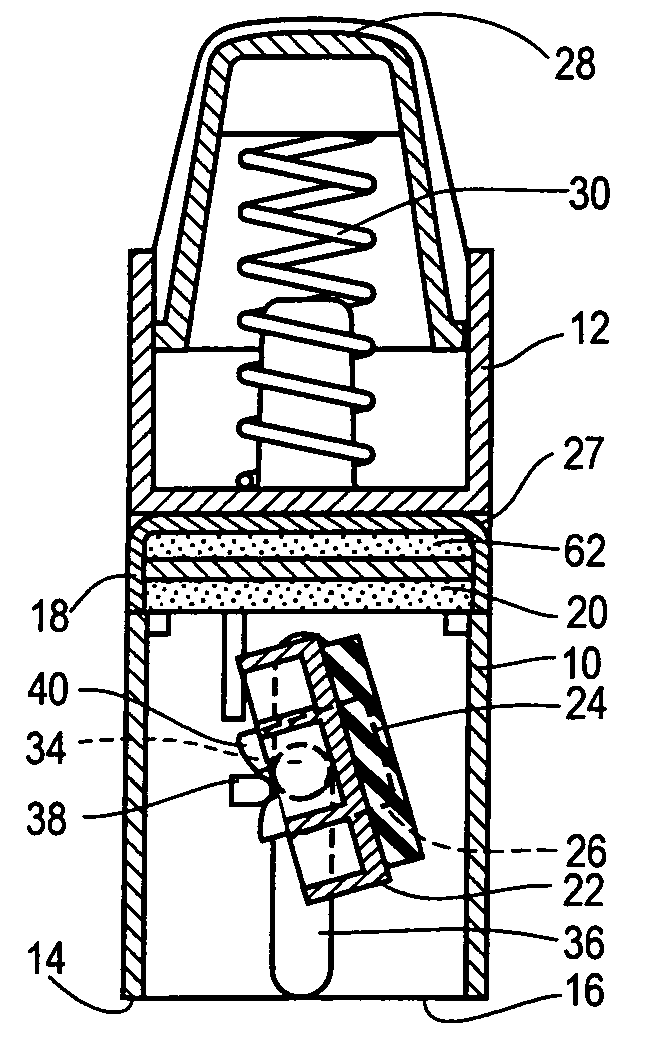
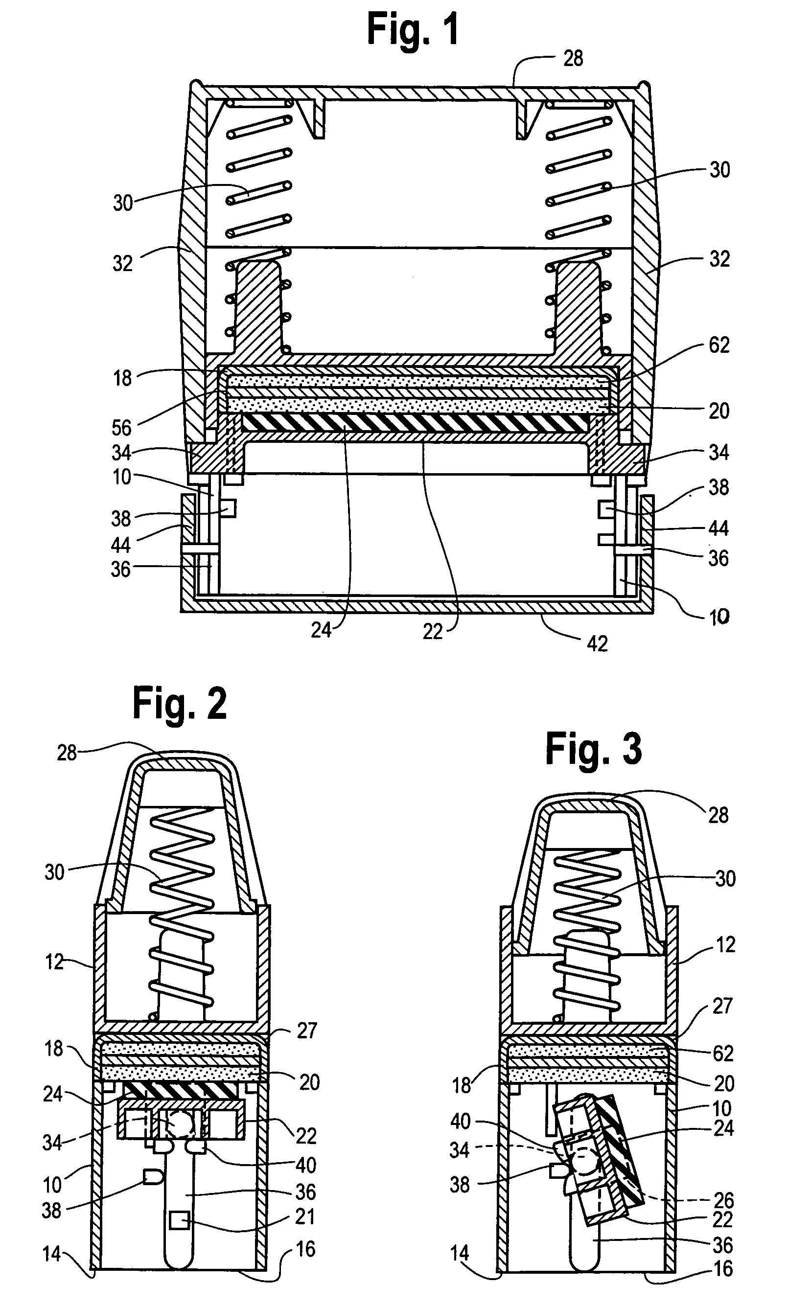
[0021]Turning first to FIGS. 1 and 2, there is illustrated a self-inking stamp comprising a lower frame part 10 and an upper frame 12. At the bottom of the lower frame is a bottom edge 14 for placing on an image receiving surface 16 to be stamped. There is an ink pad holder 18 which will be more fully described later, but for initial discussion, is seen as retaining a lower ink pad 20. A stamp insert 22 is movable to and fro between the lower ink pad 20 and the image receiving surface 16. The stamp insert 22 supports a printing plate 24 with an image forming surface 26. An actuating handle 28 is at the top of the stamp. The ink pad holder 18 is frictionally received in a slot 27 in the side of the upper frame 12 so that it can be easily slid into and out of the slot 27.

[0022]In its non-depressed state, the printing plate 24 is held in intimate contact with the lower ink pad 20 by springs 30. The actuating handle 28 surrounds the lower frame part 10 with two side legs 32 and is displ...


PUM


Abstract

An ink pad holder for use with a self-inking reciprocating hand stamp. The ink pad holder has an upper and lower compartment, with an ink pad mounted in each compartment. The ink pad holder can be inserted in the hand stamp with either ink pad facing the printing plate so that different inks can be applied to the printing plate. This allows the user greater versatility such as using the ink pad for finger printing applications by impregnating one of the ink pads with finger printing ink. Alternatively only the lower compartment may have an ink pad mounted therein with the upper compartment remaining empty for storing small items. The ink pad holder is easily removed from the hand stamp so the ink pads are easily accessible for re-inking.

Description

BACKGROUND AND SUMMARY OF THE INVENTION[0001]This invention relates to hand stamps and more particularly to a self-inking hand stamp that has an ink pad held in the stamp frame that provides ink to the image forming stamp material.[0002]One type of conventional stamp requires manufacturing a stamping member from rubber or other flexible material. The stamping member is mounted on a handle that is grasped by the user. The stamping member is placed into contact with ink, usually contained in an inkpad. The inked stamping member is then pressed against the surface onto which the stamp image is to be transferred. Repetition of the stamping process required that the stamping member be pressed against the inkpad each time an image is to be transferred. This is a disadvantage to the user as it requires extra time for each re-inking step and slows down the stamping process if many stampings are to be done. It also requires the use of an inkpad that is separate from the stamp which must be p...

Claims


Application Information

Patent Timeline
Patent Type & Authority Patents(United States)
IPC IPC(8): B41K1/54
CPCB41K1/54
Inventor PETERSEN, CRAIG J.
Owner SCHWAAB
Why Eureka
Try Eureka