Curbing machine with hopper dasher and eliptical compaction

a technology of hopper dasher and hopper, which is applied in the direction of manufacturing tools, roads, and roads, can solve the problems of curb cracks, inconvenient straight compressive force, and voids which have to be filled, so as to reduce power consumption, reduce finishing, and flexible seal

Active Publication Date: 2020-04-30
TEAM
View PDF0 Cites 6 Cited by
  • Summary
  • Abstract
  • Description
  • Claims
  • Application Information

AI Technical Summary

Benefits of technology

[0018]The compaction chamber has a rear opening in communication with a slip form through which is rearwardly directed the building material via the action of an elliptical compacting member with compaction arms; thereby depositing against the ground a formed curb which simultaneously propels the apparatus forward. As the rotary trowel compaction arms are approximately six inches in diameter, the compaction chamber and chassis frame are relatively small, making the apparatus light weight and very mobile to position a slip form against vertical surfaces or under fences.
[0034]The curbing machine described above provides an improved curb forming machine with a pivoting dasher within the hopper to prevent bridging of the cement allowing the cement to feed faster and form curb more quickly. The dasher breaks up the bridge front to back as well as side to side. The compacting member sweeps up at a shallow angle through the motion compacting the bottom as well as the top of the curb. The slip forms are easily reversible, with a design which allows for interchanging many different sizes of curb slip forms. It also has adjustable swing mounted legs and is powered by a motor with a speed reduction unit associated with a crank, connecting arm, and plunger.

Problems solved by technology

This erratic action causes voids which have to be filled.
It also causes curb cracks when the machine coasts at the end of the stroke.
However, straight compressive forces are not conducive to better compaction.
Ram machines, as the speed of the ram is increased, tend to jump ahead and then coast forward at the end of the stroke which puts cracks in the top surface of the curb.
Loose parts on the machine, such as wheels, can also leave marks in the extruded curb.
Although these devices all have various advantages and disadvantages, none have a dasher in the hopper to prevent bridging and are able to lay a continuous curb under a fence or against a vertical surface.

Method used


Image

  • Curbing machine with hopper dasher and eliptical compaction
  • Curbing machine with hopper dasher and eliptical compaction
  • Curbing machine with hopper dasher and eliptical compaction

Examples


Embodiment Construction

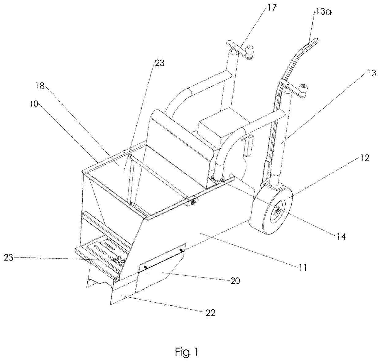
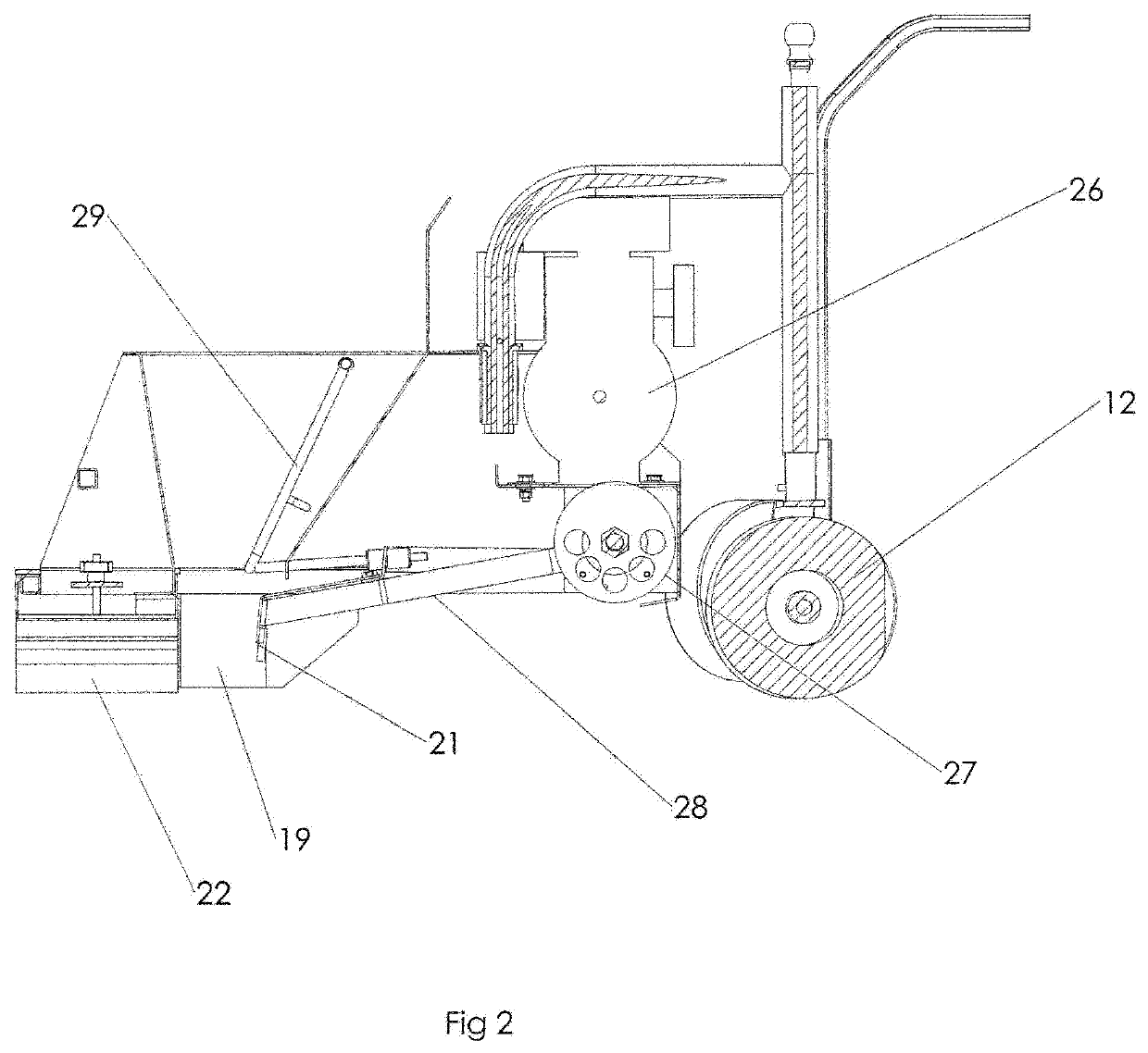
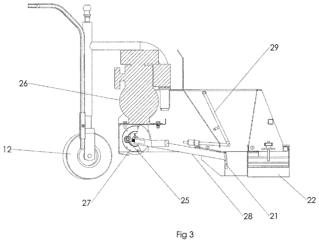
[0044]The presently preferred embodiments of the present invention will be best understood by reference to the drawings, wherein like parts are designated by like numerals throughout. It will be readily understood that the components of the present invention, as generally described and illustrated in the figures herein, could be arranged and designed in a wide variety of different configurations. Thus, the following more detailed description of the embodiments of the Curbing Machine with Hopper Dasher and Elliptical Compaction CURBING MACHINE WITH HOPPER DASHER of the present invention, as represented in FIGS. 1 through 8, is not intended to limit the scope of the invention, as claimed, but is merely representative of presently preferred embodiments of the invention.

[0045]The present invention may be embodied in other specific forms without departing from its structures, methods, or other essential characteristics as broadly described herein and claimed hereinafter. The described em...


PUM

PropertyMeasurementUnit
diameteraaaaaaaaaa
widthaaaaaaaaaa
plasticaaaaaaaaaa

Abstract

A concrete curb forming and extruding apparatus with wheel adjustment locks, and an adjustable slip form system shaping cementitious material into a continuous curb forced there through by an extruder which receives materials stored in a hopper with dasher. The extruder has a rotary trowel compacting member which continually forces material from the hopper into compressed concrete passing through an adjustable slip form to fill the same and form differing shaped continuous curbing underneath fences or against vertical surfaces or conventional curbing, depending upon the slip form setting.

Description

BACKGROUND OF THE INVENTIONField[0001]This invention relates to concrete curb forming and extruding apparatus. More particularly, it relates to a concrete curb forming and extruding apparatus with wheel adjustment locks, and an adjustable slip form system shaping cementitious material into a continuous curb forced there through by an extruder which receives materials stored in a hopper with dasher. The extruder has a rotary trowel compacting member which continually forces material from the hopper into compressed concrete passing through an adjustable slip form to fill the same and form differing shaped curbing from continuous curb underneath fences or against vertical surfaces to conventional curbing, depending upon the slip form setting.State of the Art[0002]Present concrete curb forming and extruding machines have a reciprocating ram or an auger to force concrete material into a slip form forming a running curb. The concrete material is usually of a dry consistency to hold the fo...

Claims


Application Information

Patent Timeline
Patent Type & Authority Applications(United States)
IPC IPC(8): E01C19/48
CPCB29L2031/10B29K2103/08E01C19/4893B29C48/301B29C48/265B28B3/24B29C48/30B29C48/252B28B13/0215
Inventor MCKINNON, PAUL G.MCKINNON, LANE
Owner TEAM
Why Eureka
Try Eureka