Resin impregnated continuous fiber plug with non-metallic element system

a technology of non-metallic elements and fiber plugs, which is applied in the direction of sealing/packing, fluid removal, borehole/well accessories, etc., can solve the problems of ineffective conventional sealing elements, low and high ph environment, and the element systems of downhole tools, so as to achieve the effect of reducing drilling difficulty and reducing drilling difficulty

Inactive Publication Date: 2006-10-24
WEATHERFORD TECH HLDG LLC
View PDF138 Cites 96 Cited by
  • Summary
  • Abstract
  • Description
  • Claims
  • Application Information

AI Technical Summary

Benefits of technology

[0012]A non-metallic element system is provided which can effectively seal or pack-off an annulus under elevated temperatures. The element system can also resist high differential pressures as well as high and low pH environments without sacrificing performance or suffering mechanical degradation. Further, the non-metallic element system will drill up considerably faster than a conventional element system that contains metal.

Problems solved by technology

One problem associated with conventional element systems of downhole tools arises in high temperature and / or high pressure applications.
Another problem with conventional element systems occurs in both high and low pH environments.
In these extreme downhole conditions, conventional sealing elements become ineffective.
Most often, the physical properties of the sealing element suffer from degradation due to extreme downhole conditions.
Yet another problem associated with conventional element systems of downhole tools arises when the tool is no longer needed to seal an annulus and must be removed from the wellbore.
Rather than de-actuate the tool and bring it to the surface of the well, the tool is typically destroyed with a rotating milling or drilling device.
The more metal parts making up the tool, the longer the milling operation takes.
Metallic components also typically require numerous trips in and out of the wellbore to replace worn out mills or drill bits.

Method used


Image

  • Resin impregnated continuous fiber plug with non-metallic element system
  • Resin impregnated continuous fiber plug with non-metallic element system
  • Resin impregnated continuous fiber plug with non-metallic element system

Examples


Embodiment Construction

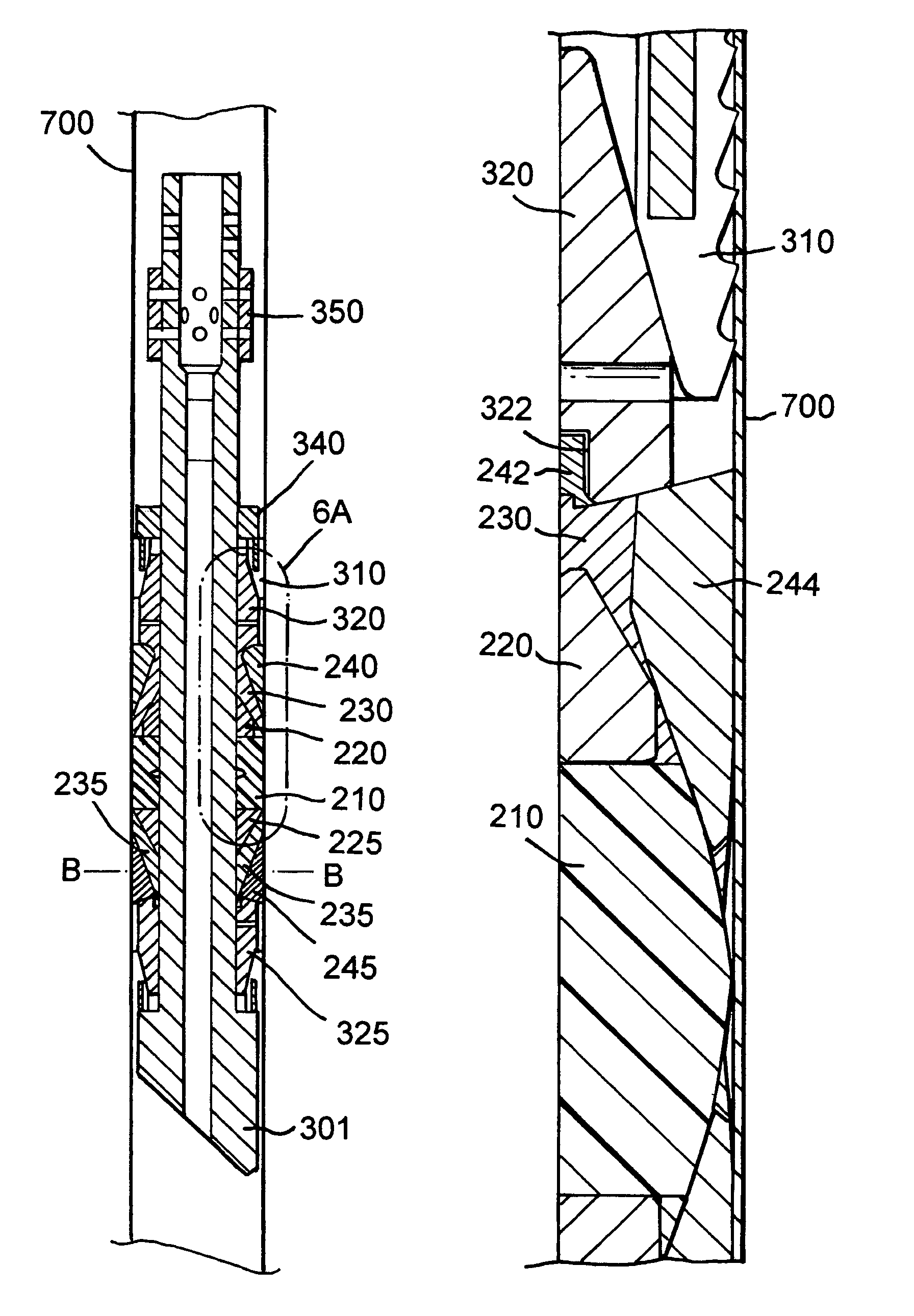
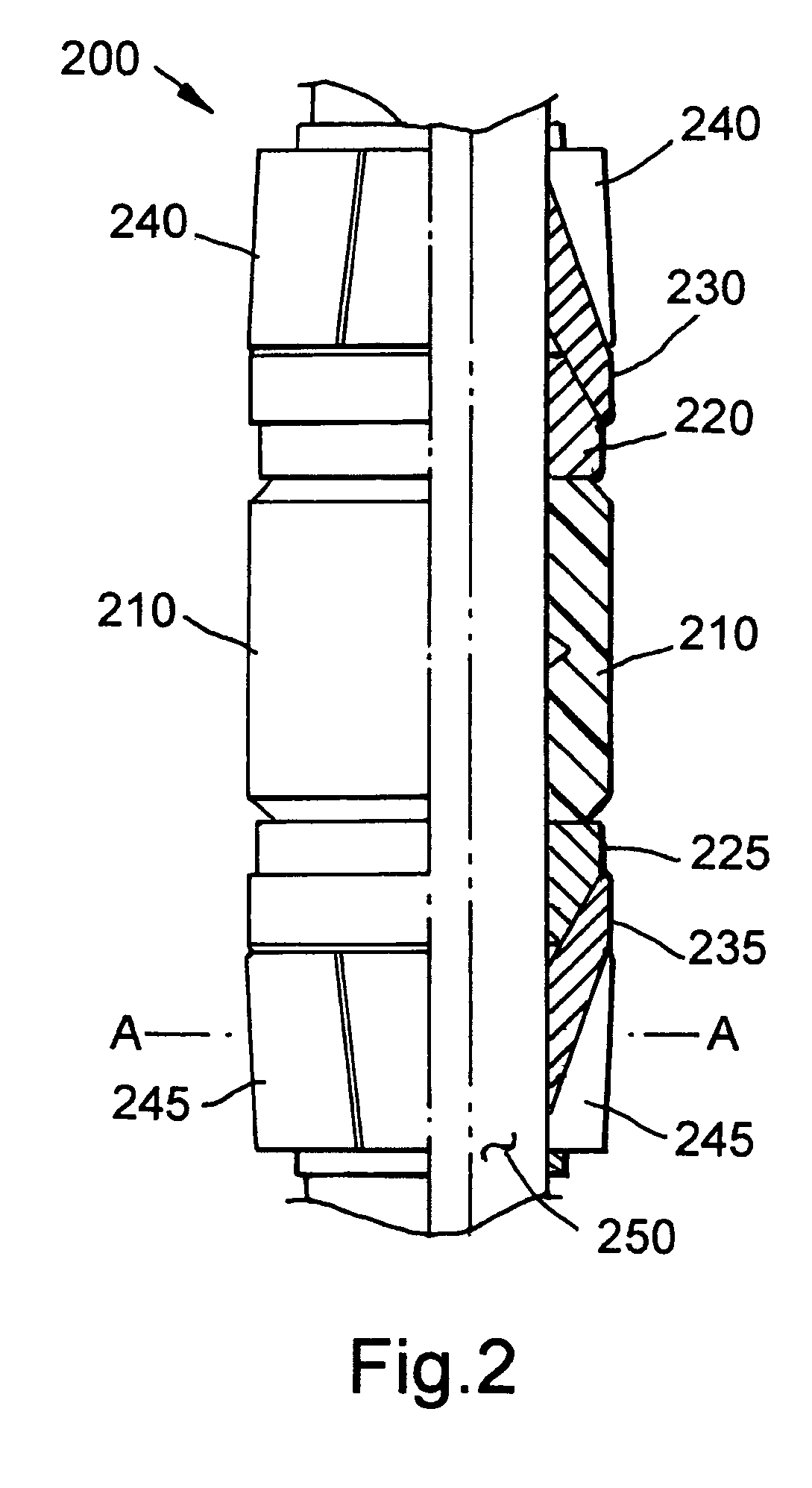
[0026]A non-metallic element system that is capable of sealing an annulus in very high or low pH environments as well as at elevated temperatures and high pressure differentials is provided. The non-metallic element system is made of a fiber reinforced polymer composite that is compressible and expandable or otherwise malleable to create a permanent set position.

[0027]The composite material is constructed of a polymeric composite that is reinforced by a continuous fiber such as glass, carbon, or aramid, for example. The individual fibers are typically layered parallel to each other, and wound layer upon layer. However, each individual layer is wound at an angle of about 30 to about 70 degrees to provide additional strength and stiffness to the composite material in high temperature and pressure downhole conditions. The tool mandrel is preferably wound at an angle of 30 to 55 degrees, and the other tool components are preferably wound at angles between about 40 and about 70 degrees. ...


PUM

PropertyMeasurementUnit
phase angleaaaaaaaaaa
angleaaaaaaaaaa
pressuresaaaaaaaaaa

Abstract

A non-metallic element system is provided which can effectively seal or pack-off an annulus under elevated temperatures. The element system can also resist high differential pressures without sacrificing performance or suffering mechanical degradation, and is considerably faster to drill-up than a conventional element system. In one aspect, the composite material comprises an epoxy blend reinforced with glass fibers stacked layer upon layer at about 30 to about 70 degrees. A downhole tool, such as a bridge plug, frac-plug, or packer, is also provided. The tool comprises a first and second support ring having one or more tapered wedges, a first and second expansion ring, and a sealing member disposed between the expansion rings and the support rings.

Description

CROSS-REFERENCE TO RELATED APPLICATIONS[0001]This application is a continuation of co-pending U.S. patent application Ser. No. 10 / 811,559, filed on Mar. 29, 2004, which is a continuation of U.S. patent application Ser. No. 09 / 893,505, filed on Jun. 27, 2001, now U.S. Pat. No. 6,712,153. Both related applications are incorporated by reference herein.BACKGROUND OF THE INVENTION[0002]1. Field of the Invention[0003]The present invention relates to a downhole non-metallic sealing element system. More particularly, the present invention relates to downhole tools such as bridge plugs, frac-plugs, and packers having a non-metallic sealing element system.[0004]2. Background of the Related Art[0005]An oil or gas well includes a wellbore extending into a well to some depth below the surface. Typically, the wellbore is lined with tubulars or casing to strengthen the walls of the borehole. To further strengthen the walls of the borehole, the annular area formed between the casing and the borehol...

Claims


Application Information

Patent Timeline
Patent Type & Authority Patents(United States)
IPC IPC(8): E21B33/12
CPCE21B33/1208Y10T29/49885
Inventor TURLEY, ROCKY A.FISHBECK, CRAIGOUDAT, RAMI ALZIMMERMAN, PATRICK J.PARKER, CHARLES D.NIKLASCH, MICHAEL R.ELDRIDGE, WILLIAM J.FREIHET, ROLANDHINES, III, WILLIAM F.MURRAY, BILL
Owner WEATHERFORD TECH HLDG LLC
Why Eureka
Try Eureka