Overflow assembly for bathtubs and the like

Inactive Publication Date: 2006-10-31
WCM IND INC
View PDF16 Cites 52 Cited by
  • Summary
  • Abstract
  • Description
  • Claims
  • Application Information

AI Technical Summary

Benefits of technology

[0006]A further object of the invention is to facilitate the testing procedure of the overflow system before the final

Problems solved by technology

In new building construction, the plumbers prefer not to put the finished closure valves in the bottom of tubs, or the finished decorative plate over the overflow outlet at the end, of the tub until the project is finished because these elements will be ofte

Method used


Image

  • Overflow assembly for bathtubs and the like
  • Overflow assembly for bathtubs and the like
  • Overflow assembly for bathtubs and the like

Examples


Embodiment Construction

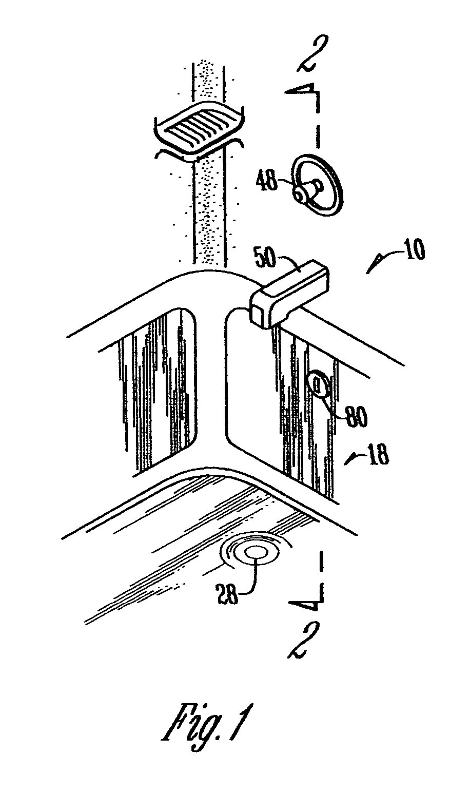
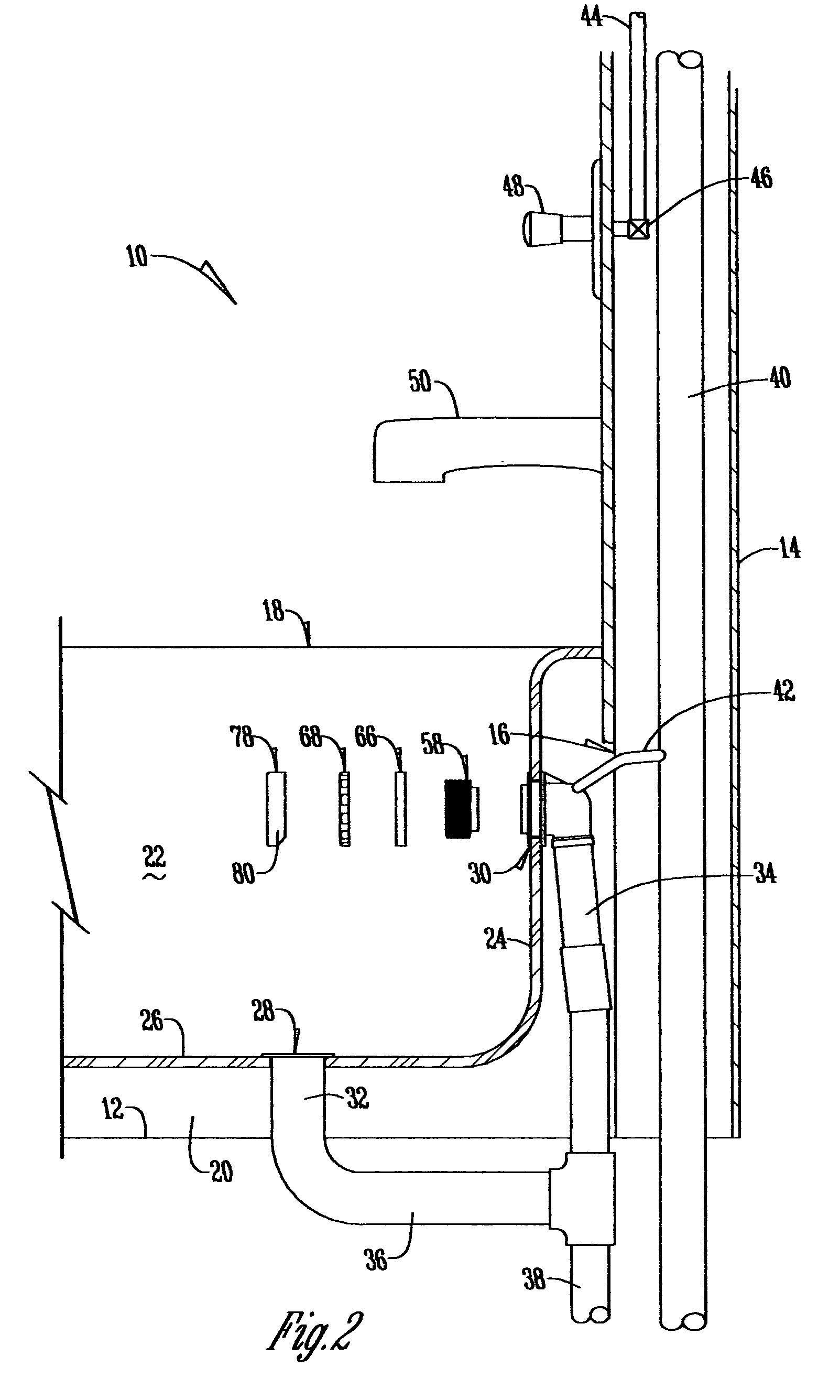
[0022]With reference of FIGS. 1 and 2, a conventional bathroom structure 10 has a floor 12, and a hollow wall 14 with a wall opening 16 therein. A conventional bathtub (“tub”) 18 has a base 20 which rests upon floor 12. Sidewalls 22 extend upwardly from base 20 as does an end wall 24. The end walls 24 extend upwardly from the bottom 26, perpendicular to the side walls 22, and have an outer surface. A bottom 26 dwells in spaced relation to the floor 12.

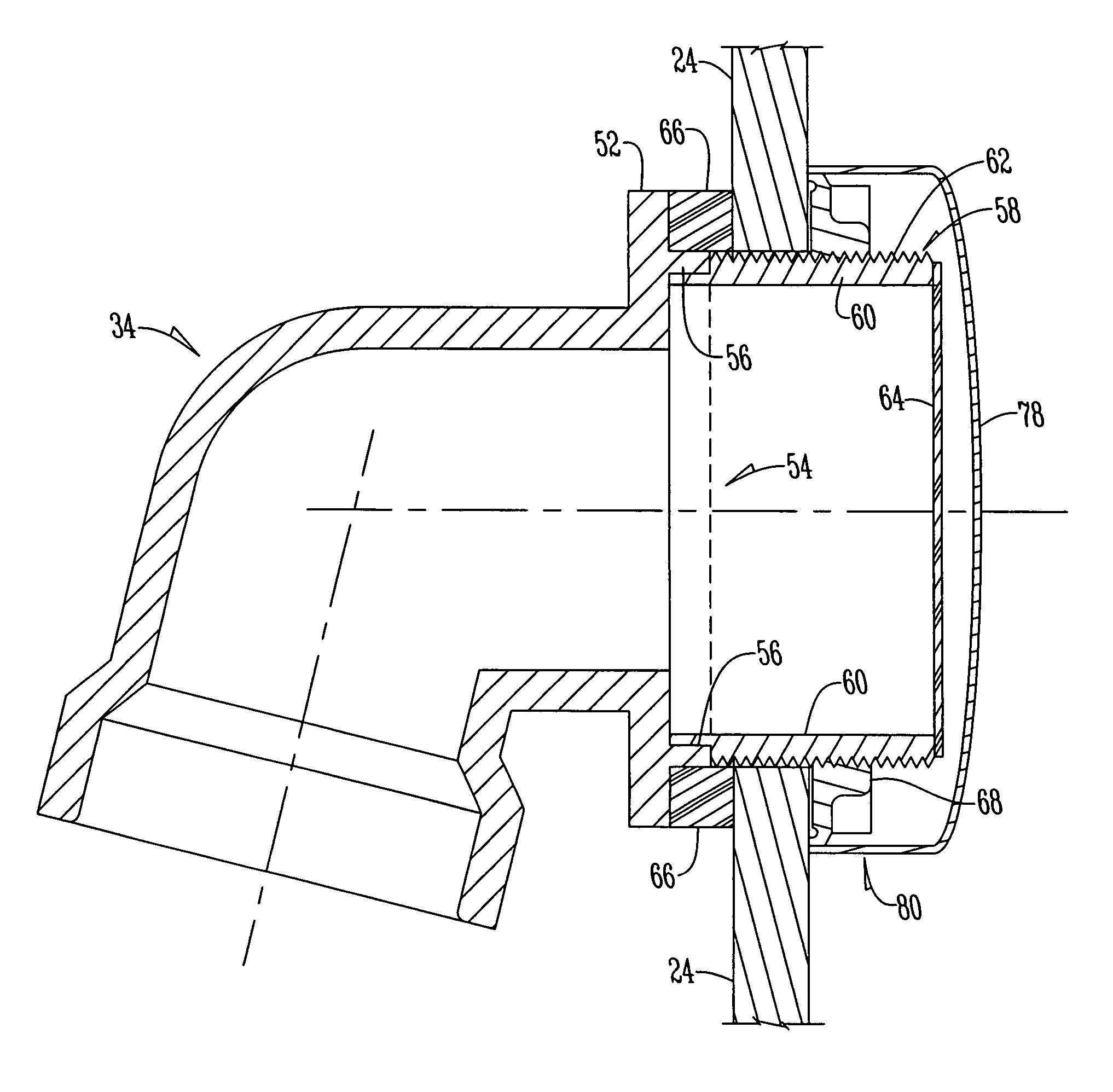
[0023]A conventional drain port 28 is located in bottom 26. A conventional overflow port 30 is located in the end wall 241 (FIG. 2). A vertical drain pipe 32 extends downwardly from drain port 28, and overflow drain pipe 34 extends downwardly from overflow port 30. A horizontal pipe 36 connects pipes 32 and 34. A drain pipe 38 extends downwardly from the junction between pipes 34 and 36.

[0024]A conventional vertical vent pipe 40 is located within the hollow wall 14. Pipe 42 interconnects vent pipe 40 and the upper end of overflow drain...


PUM


Abstract

An overflow system in the bathtub has an overflow port and has a drain pipe in connection with the overflow port. A threaded flange has a stub shoulder on one end which is fitted into a circular sleeve on the overflow port. The threaded flange has exterior threads on its outer surface and a thin diaphragm secured to the end thereof opposite to the stub shoulder. A large sealing washer embraces the outside of the circular flange on the overflow port and extends partially over the threads of the threaded flange. A large internally threaded nut is threadably mounted on the outer end of the threaded flange and compresses the sealing washer against a vertical flange on the port to seal the connection between the threaded flange and the port. A decorative cap is frictionally snapped into engagement with protrusions on the outer surface of the nut. The cap can be removed when needed to permit the plumber to gain access to the diaphragm to cut it open for fluid flow after the system has been tested for leaks, or put in place after the cut takes place.

Description

CROSS REFERENCE TO RELATED APPLICATIONS[0001]This application is a continuation of U.S. patent application Ser. No. 10 / 674,862, filed Sep. 30, 2003 which is a continuation-in-part of U.S. patent application Ser. No. 10 / 229,533 filed Aug. 28, 2002 now U.S. Pat. No. 6,675,406.BACKGROUND OF THE INVENTION[0002]In new building construction, the plumbers prefer not to put the finished closure valves in the bottom of tubs, or the finished decorative plate over the overflow outlet at the end, of the tub until the project is finished because these elements will be often damaged as the construction project is brought to a close. Further, the piping for both of the outlets needs to be checked for leaks before the inspection process is completed. The test involves running water down the vent for the drain until it reaches a level above the tub and the tester then determines whether any of the piping leaks. Thus, when the testing operation arrives, a plug is put in the bottom drain of the tub an...

Claims


Application Information

Patent Timeline
IPC IPC(8): E03C1/24
CPCE03C1/24
Inventor BALL, WILLIAM T
Owner WCM IND INC
Why Eureka
Try Eureka