
Flooring and method for laying and manufacturing the same

a technology of locking system and floorboard, which is applied in the direction of resiliently mounted floors, walls, flooring, etc., can solve the problems of inability to join the floorboard, inability to lay traditional parquet patterns, and relatively slow manufacturing operation of machining using a shank-end mill, so as to achieve fast and easy joining, advantageous, fast and efficient laying

Inactive Publication Date: 2006-10-31
VÄLINGE INNOVATION AB
View PDF287 Cites 168 Cited by
  • Summary
  • Abstract
  • Description
  • Claims
  • Application Information

AI Technical Summary

Benefits of technology

[0019]An advantage of the present invention is that floorboards can be laid long side against short side in advanced patterns and that joining can be made quickly and easily in all the laying alternatives that may be used when laying in all four directions from a center.
[0020]The mirror-inverted joint systems need not be identical to allow joining. Surfaces that are not active in the vertical and horizontal locking means may, for instance, have a deviating shape. For example, the outer part of the tongue and the inner part of the groove may be varied.
[0021]According to a second aspect, the present invention comprises a system for making a flooring, which comprises quadrangular floorboards which are mechanically lockable, in which system the individual floorboards along their four edge portions have pairs of opposing connecting means for joining together similar, adjoining floorboards at least vertically, and wherein the pairs of opposing connecting means of the floorboards at least in a first direction in the plane of the floorboard are designed so as to allow locking-together both horizontally and vertically by inward angling and / or snapping-in. Moreover also this system comprises two different types of floorboard, the connecting means of one type of floorboard along one pair of opposite edge portions being arranged in a mirror-inverted manner relative to the corresponding connecting means along the same pair of opposite edge portions of the other type of floorboard.
[0022]According to a third aspect, the present invention comprises a flooring, which is formed by means of one of the systems described above. According to a fourth aspect, the present invention comprises a set of floorboards for making such a flooring. Such a set may be advantageous in terms of distribution since a customer, by buying such a set, can obtain a set of floorboards which are adjusted to each other. This is particularly advantageous if variations may appear in the manufacturing process as regards, for instance, the color of the surface or the tolerances of the connecting means.
[0023]According to a fifth aspect, the present invention comprises fitting pieces, which have at least one oblique edge and which along their edge portions have connecting means for cooperation with adjoining floorboards. Such fitting pieces may constitute an important aid in installation of a floor with an advanced pattern, such as a herringbone pattern, by the possibility of quickly and efficiently laying floorboards at an angle other than 90° with each other. Since also the fitting pieces are provided with connecting means, a herringbone flooring can be obtained, where both the frame and the actual herringbone pattern are mechanically locked together so that the entire floor is held together mechanically.
[0024]According to a sixth aspect, the invention comprises a locking strip for interconnecting floorboards provided with identical locking means. This can be an aid, for instance, in the cases where a fitting piece is not available or if one chooses to form all fitting pieces with identical connecting means all the way round, for instance with a view to reducing the number of variants of fitting pieces.

Problems solved by technology

Thus the boards cannot be joined locking element against locking element or locking groove against locking groove.
Using this technique, it is thus not possible to lay traditional parquet patterns where the boards are joined long side against short side in “herringbone pattern” or in different forms of diamond patterns.
This is a drawback since machining using a shank-end mill is a relatively slow manufacturing operation.
However, it is not shown how a complete floor can be joined using such floorboards to form a pattern.
The manufacture is complicated, and nor can they be used to provide the desired pattern.

Method used


Image

  • Flooring and method for laying and manufacturing the same
  • Flooring and method for laying and manufacturing the same
  • Flooring and method for laying and manufacturing the same

Examples


Embodiment Construction

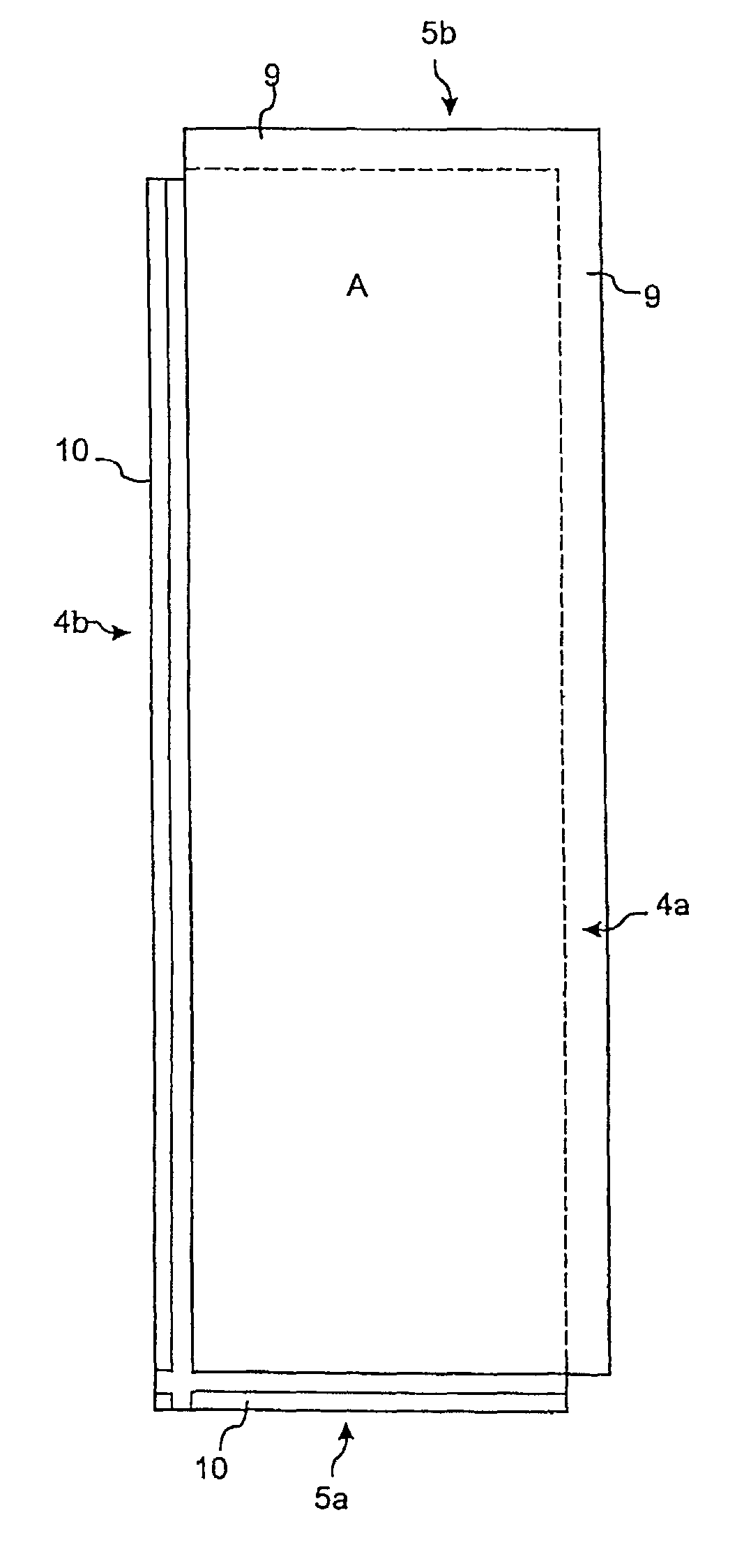
[0045]In the following description, the two types of floorboard according to the invention will be designated A and B, respectively. This aims merely at illustrating the cooperation between two types of floorboard. Which type of board is designated A and B respectively is immaterial to the invention.

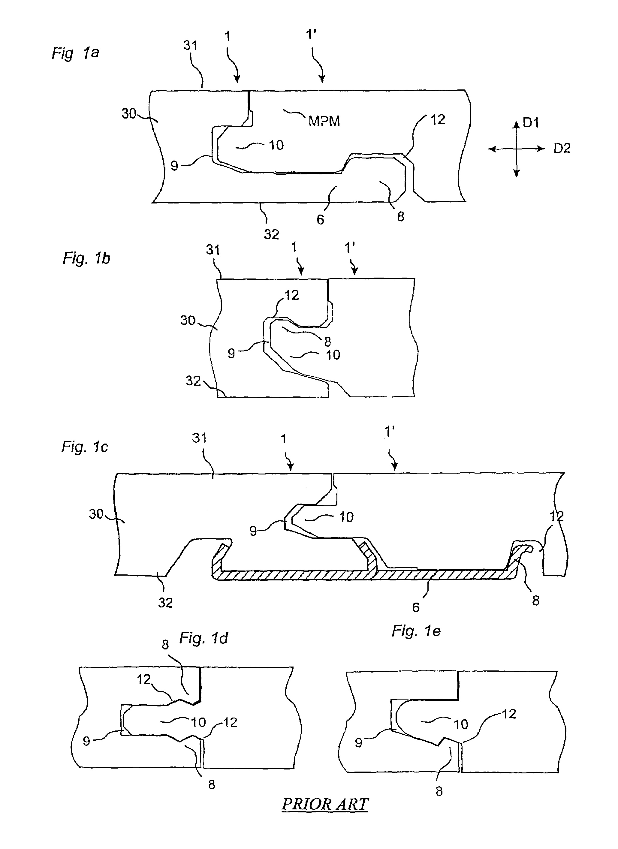
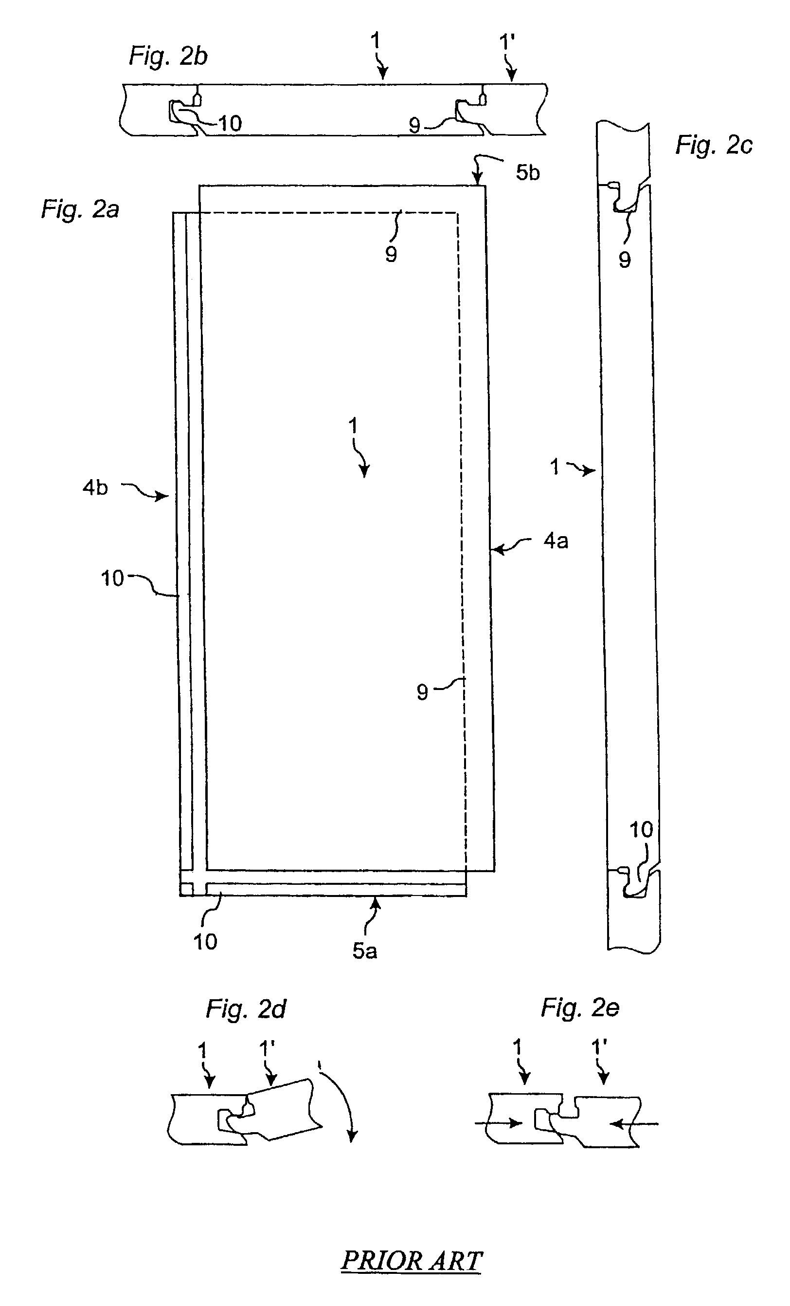
[0046]FIGS. 1a–e illustrate floorboards 1, 1′ with a surface 31, a core 30 and a rear side 32, whose joint edge portions are provided with prior-art mechanical joint systems. The vertical locking means comprise a groove 9 and a tongue 10. The horizontal locking means comprise locking elements 8 which cooperate with locking grooves 12. The joint systems according to FIGS. 1a and 1c have on the rear side 32 a strip 6 which supports or is formed integrally with the locking element 8. The locking systems according to FIGS. 1b, d and e are distinguished by the locking element 8 and the locking groove 12 being formed in the groove / tongue. The locking systems according to FIGS. 1a–1c can be joi...


PUM

PropertyMeasurementUnit
angleaaaaaaaaaa
angleaaaaaaaaaa
displacementaaaaaaaaaa

Abstract

Floorboards for installation of floors in herringbone pattern are formed with two opposite sides inverted relative to each other. The invention further comprises methods for producing and making floorings comprising such floorboards, as well as fitting pieces and sets of parts for such floorings.

Description

BACKGROUND[0001]1. Technical Field[0002]The invention relates generally to the technical field of locking systems for floorboards. The invention concerns on the one hand a locking system for floorboards which can be joined mechanically in different patterns and, on the other hand, floorboards provided with such a locking system and various methods of installation. The invention is particularly suited for use in mechanical locking systems integrated with the floorboard, for instance, of the types described and shown in WO94 / 26999, WO96 / 47834, WO96 / 27721, WO99 / 66151, WO99 / 66152, WO00 / 28171, SE0100100-7 and SE0100101-5 which are herewith incorporated by reference, but is also usable in other joint systems for joining of flooring. More specifically, the invention relates to locking systems which enable laying of mainly floating floors in advanced patterns.[0003]The present invention is particularly suited for use in floating wooden floors, such as massive wooden floors or parquet floors...

Claims


Application Information

Patent Timeline
Patent Type & Authority Patents(United States)
IPC IPC(8): E04B1/38E04F15/02E04F15/04
CPCE04C2/20E04F15/02E04F15/02033E04F15/04E04F2201/0115E04F2201/0153Y10T29/49E04F2201/026E04F2201/027E04F2201/042E04F2201/0517Y10T409/303752E04F2201/023
Inventor PERVAN, DARKOPERVAN, TONY
Owner VÄLINGE INNOVATION AB
Learn More