Heat-transfer interface device between a source of heat and a heat-receiving object

a heat-transfer interface and heat-receiving object technology, applied in the direction of lighting and heating apparatus, natural mineral layered products, cellulosic plastic layered products, etc., can solve the problems of warping, deformation of the entire interface device, and impair the interface conditions, so as to improve the stability of the heat-transfer interface, improve the heat-transfer conditions, and ensure the effect of heat-transfer stability

Inactive Publication Date: 2006-11-21
PACIFIC RUBBER & PACKING
View PDF14 Cites 39 Cited by
  • Summary
  • Abstract
  • Description
  • Claims
  • Application Information

AI Technical Summary

Benefits of technology

[0012]It is an object of the invention to provide a heat-transfer interface device between a source of heat and a heat-receiving object for controlling and stabilizing heat transfer conditions. It is another object to provide the aforementioned heat-transfer interface device for use under conditions of heat transfer between the parts made from materials with different physical properties. Still another object is to provide the aforementioned heat-transfer interface device, in which heat-transfer conditions remain unchanged even when the aforementioned parts are thermally deformed within the range of working temperatures up to 350° C. A further object is to provide the aforementioned device wherein stable heat-transfer conditions are achieved by imparting a special shape to at least one of the contacting members of the interface device. It is another object to provide a reliable and stable thermally-conductive and electrically non-conductive interface between the RF coil and the top of the RF reactor. Still another object is to provide the aforementioned assembly, which ensures generation of uniform plasma and thus uniform plasma treatment in the inductively coupled plasma reactor. A further object is to provide the aforementioned device that incorporates RF coils and heating elements embedded into an elastic material filled with thermally conductive and electrically non-conductive filler. It is another object is to provide an elastomeric interface that can operate at temperatures over 200° C. A further object is to provide a method for improving and stabilizing a heat-transfer interface between the RF coil and the inductively coupled plasma reactor. Another object is to provide a method for stabilization and improvement of heat transfer conditions between the external source of heat and the interior of the processing chamber.
[0015]Furthermore, when the elastomer is compressed, it develops anisotropy in the direction of the compression. Since the material of the elastomer is filled with finely dispersed powder or fibers, the aforementioned compression will at least partially protect the heat-transfer device from the loss of thermal conductivity. The assembly can also be used for removal of heat from the RF coils and from the interior of the plasma-generation chamber by passing through the hollow coils a cooling medium and transferring the heat to the surrounding environment through the thermally conductive elastomers. The cooler / heater element is made hollow for circulation of the heating / cooling medium in order to selectively use this element for cooling or for heating the working gas in the plasma-generation chamber. Alternatively, the supply of the cooling medium can be discontinued, and the cooler / heater element and / or the hollow RF coil can be activated for transfer of heat to the plasma chamber in order to increase the temperature of the working gas in the chamber. If necessary, the heat transfer medium can be used for cooling the working gas in the plasma generation chamber.

Problems solved by technology

Since the elastomeric material is fixed, when the temperature of the elastomer is increased, the compression force is reduced, and under the effect of thermal deformations the entire interface device is deformed and is subjected to warping, sagging and formation of free volume that could impair the interface conditions.

Method used


Image

  • Heat-transfer interface device between a source of heat and a heat-receiving object
  • Heat-transfer interface device between a source of heat and a heat-receiving object
  • Heat-transfer interface device between a source of heat and a heat-receiving object

Examples


Embodiment Construction

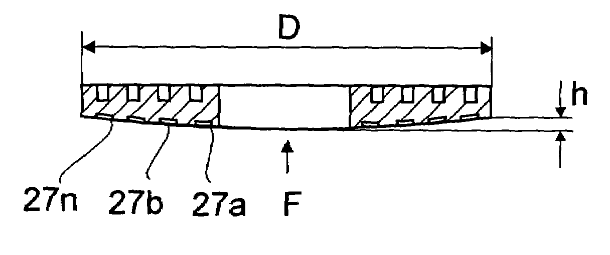
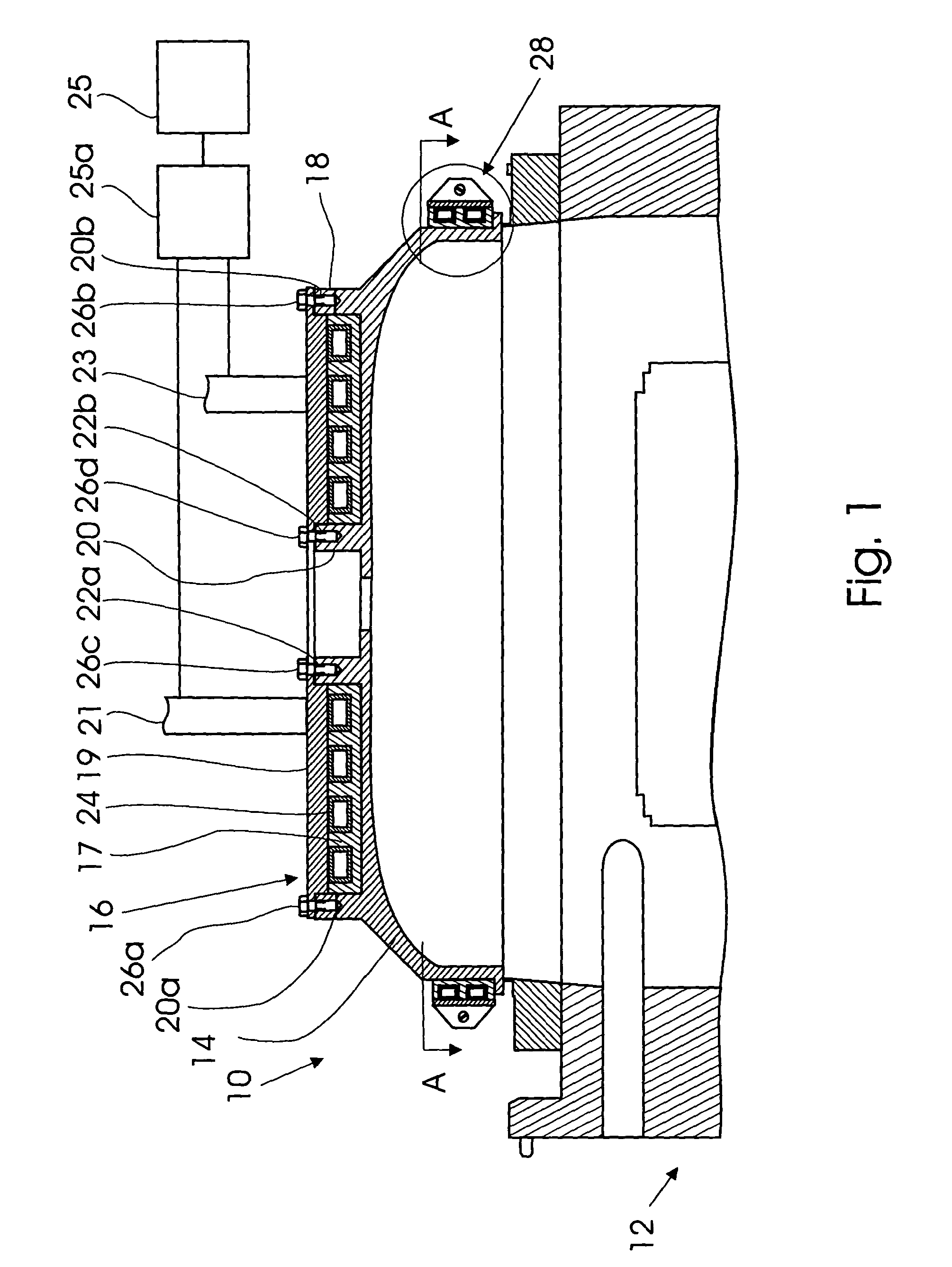
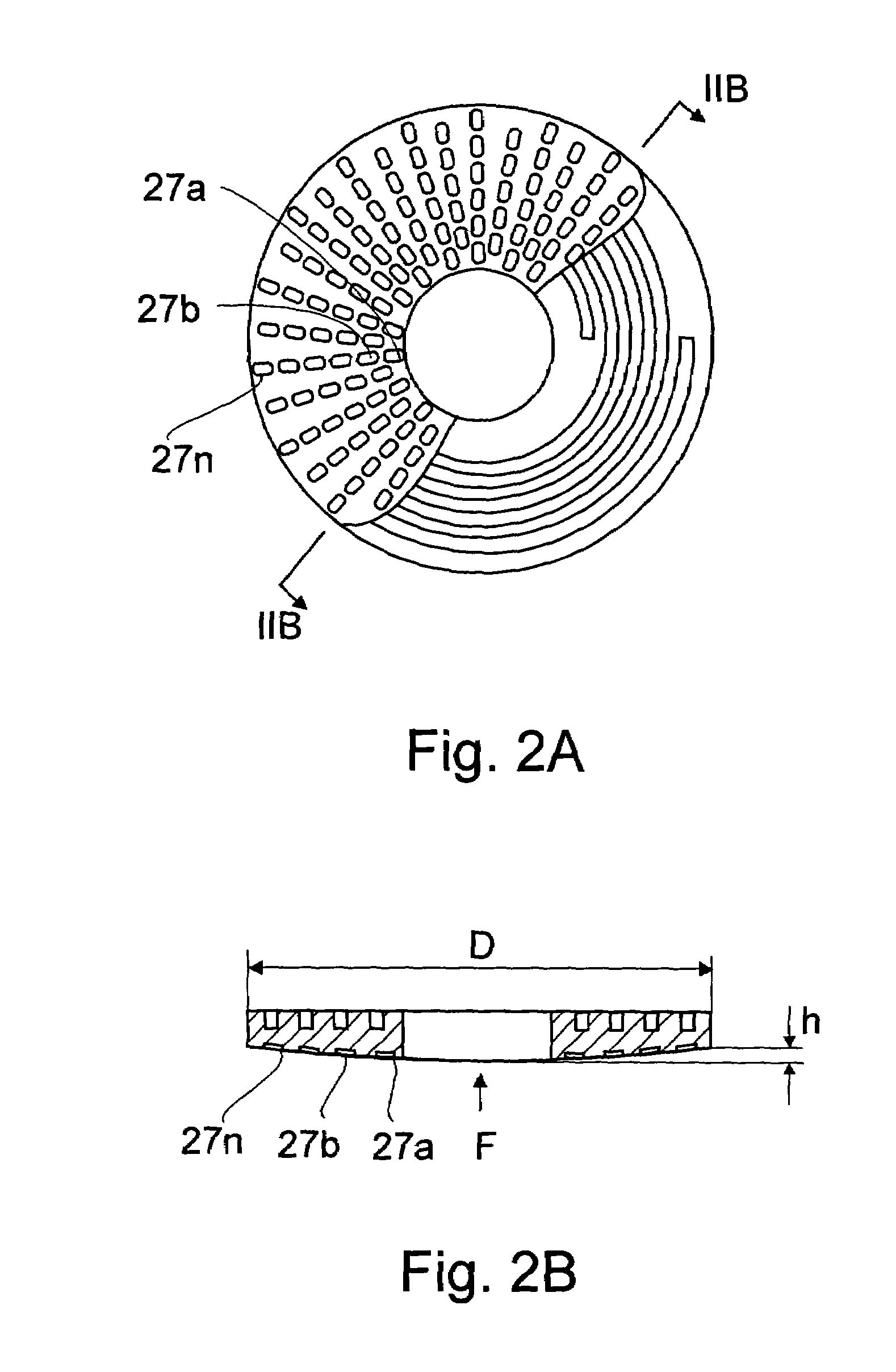
[0023]FIG. 1 is a vertical sectional view of an ICP reactor equipped with the coil assembly of the invention. It is understood that the ICP reactor is shown only as one of possible applications of the heat-transfer interface device of the invention. In this drawing, the ICP reactor, which as a whole is designated by reference numeral 10, consists of a sealed ICP reactor housing 12 made from a dielectric material, e.g., a ceramic, and connected to a vacuum system and to a working gas supply system (not shown in FIG. 1). The upper open side of the housing 12 is sealingly closed with a dome-like ceramic cover 14 which in general has the same shape and construction as a conventional reactor housing cover, with the exception that the external top surface of the cover 14 has a specific shape for accommodation of a heat-transfer interface device 16 of the invention. More specifically, the cover has an outer vertical cylindrical project 18 and an inner vertical cylindrical projection 20 whi...


PUM

PropertyMeasurementUnit
temperatureaaaaaaaaaa
temperaturesaaaaaaaaaa
frequencyaaaaaaaaaa

Abstract

What is proposed is a heat-transfer interface device for use in a range of up 320° C. working temperatures for transfer of heat from a source of heat to a heat-receiving object under severe conditions. The device comprises an elastomeric material filled with an electrically-nonconductive and thermally-conductive filler material. The elastomeric material may have recesses on the surface or the surface may be curved, e.g., on the side facing the source of heat for forming a space between the surface of the device and the mating surface of the source of heat. The elastomeric material is clamped between the heat source and heat receiver in a compressed state so that when it is expanded under the effect of an increased temperature, the material is redistributed and the recesses are flattened. The elastomeric material comprises perfluoroelastomer polymer, and the filler can be selected from boron nitride, aluminum nitride, beryllium oxide, etc. If necessary, a combined mixing-assisting and compression-set reducing agent in the form of perfluoropolyether can be added.

Description

FIELD OF THE INVENTION[0001]The present invention relates to a device and method for controlling and stabilizing heat-transfer conditions between the heat source and heat-receiving object, in particular to a device and method for controlling and stabilizing heat-transfer conditions in apparatuses in which the main process is associated with generation and transfer of heat and in which stability of heat-transfer conditions is a critical factor for normal operation of the apparatus. The invention may find use in applications where heat is transferred through an electrically insulated interface between parts made of materials with different physical properties such as coefficient of thermal expansion.BACKGROUND OF THE INVENTION[0002]In many circumstances, reliable and stable removal of heat from a source of heat to the surrounding environment, as well as delivery of heat to a working chamber of a processing apparatus may be a critical issue, wherein violation of normal thermal conditio...

Claims


Application Information

Patent Timeline
Patent Type & Authority Patents(United States)
IPC IPC(8): F28F7/00F28F13/00H01J37/32
CPCF28F13/00H01J37/32522H01J37/321Y10T428/2991Y10T428/3154
Inventor FAYBISHENKO, VICTORBURFIELD, ASHLEY
Owner PACIFIC RUBBER & PACKING
Why Eureka
Try Eureka