Compound helicopter with combined wings and landing struts

a helicopter and landing strut technology, applied in the field of helicopters, can solve the problems of wing tips flying, wing tips fluttering, wing tips not significantly increasing rotor efficiency during hovering, etc., and achieve the effect of reducing the blockage of the main rotor downwash

Active Publication Date: 2006-11-21
NORTHROP GRUMMAN SYST CORP
View PDF7 Cites 15 Cited by
  • Summary
  • Abstract
  • Description
  • Claims
  • Application Information

AI Technical Summary

Problems solved by technology

Compound helicopters, having wings to provide lift during horizontal flight, loose efficiency during hover because of the disruption of downwash from the main rotor.
The problem is that with no locking feature the wing tips will flutter.
Furthermore, just rotating the wing tips will not significantly increase rotor efficiency during hover.
Furthermore, separate landing apparatus is still required.

Method used


Image

  • Compound helicopter with combined wings and landing struts
  • Compound helicopter with combined wings and landing struts
  • Compound helicopter with combined wings and landing struts

Examples


Embodiment Construction

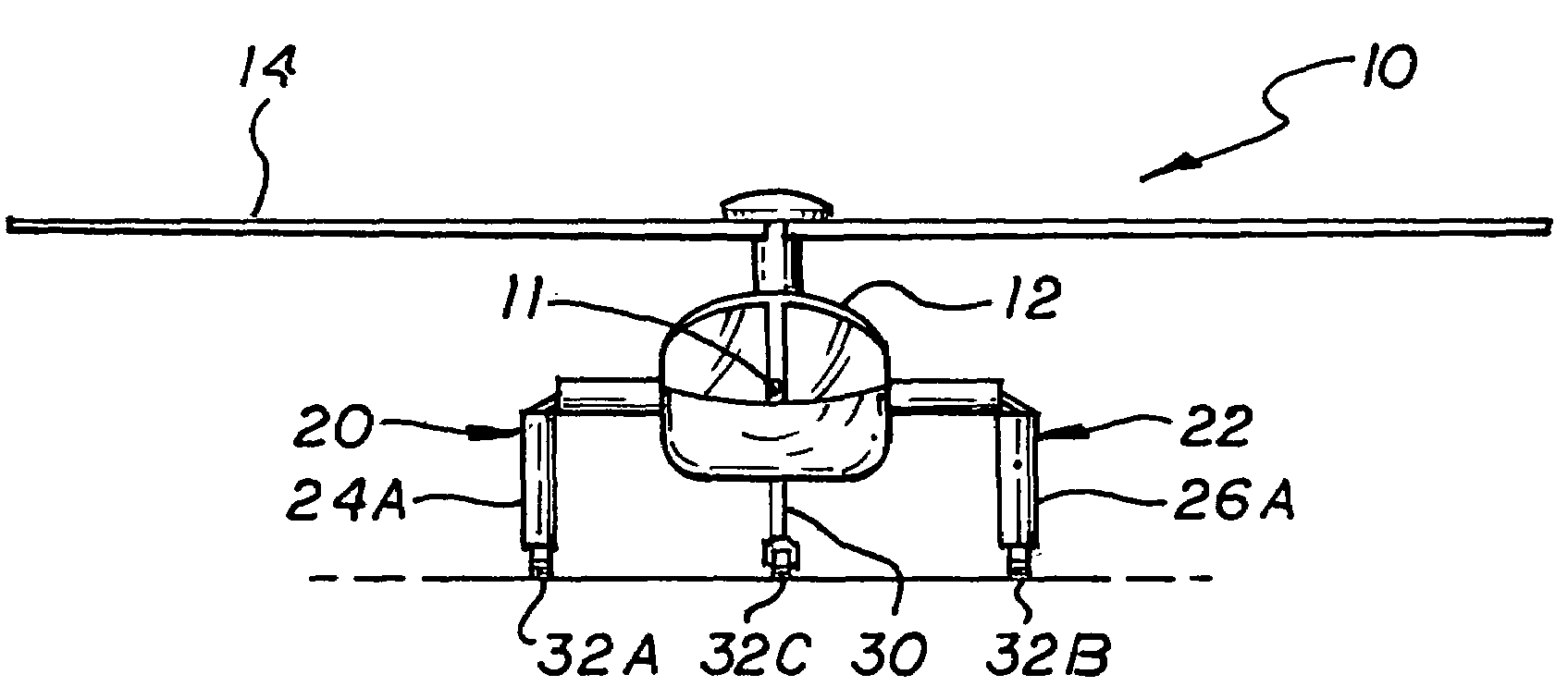
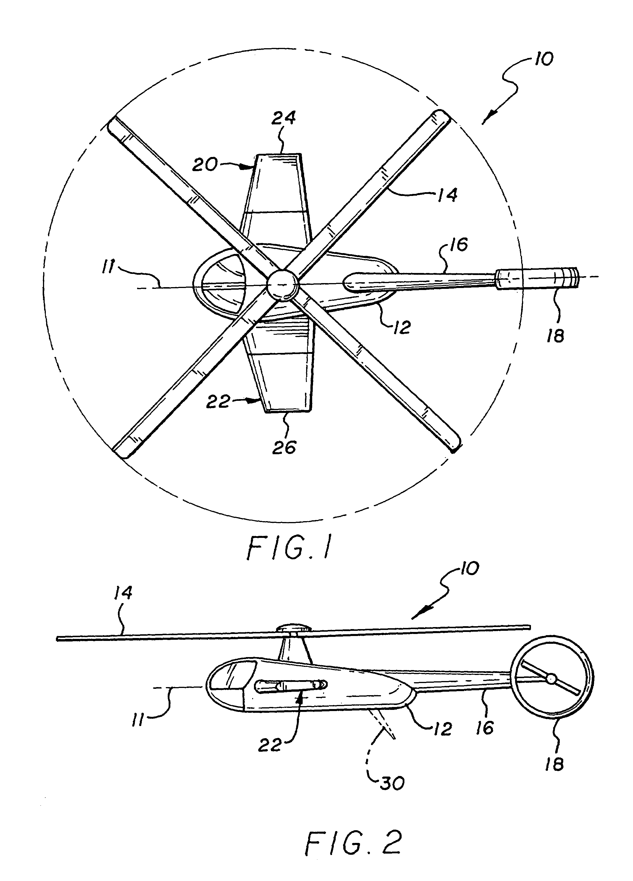
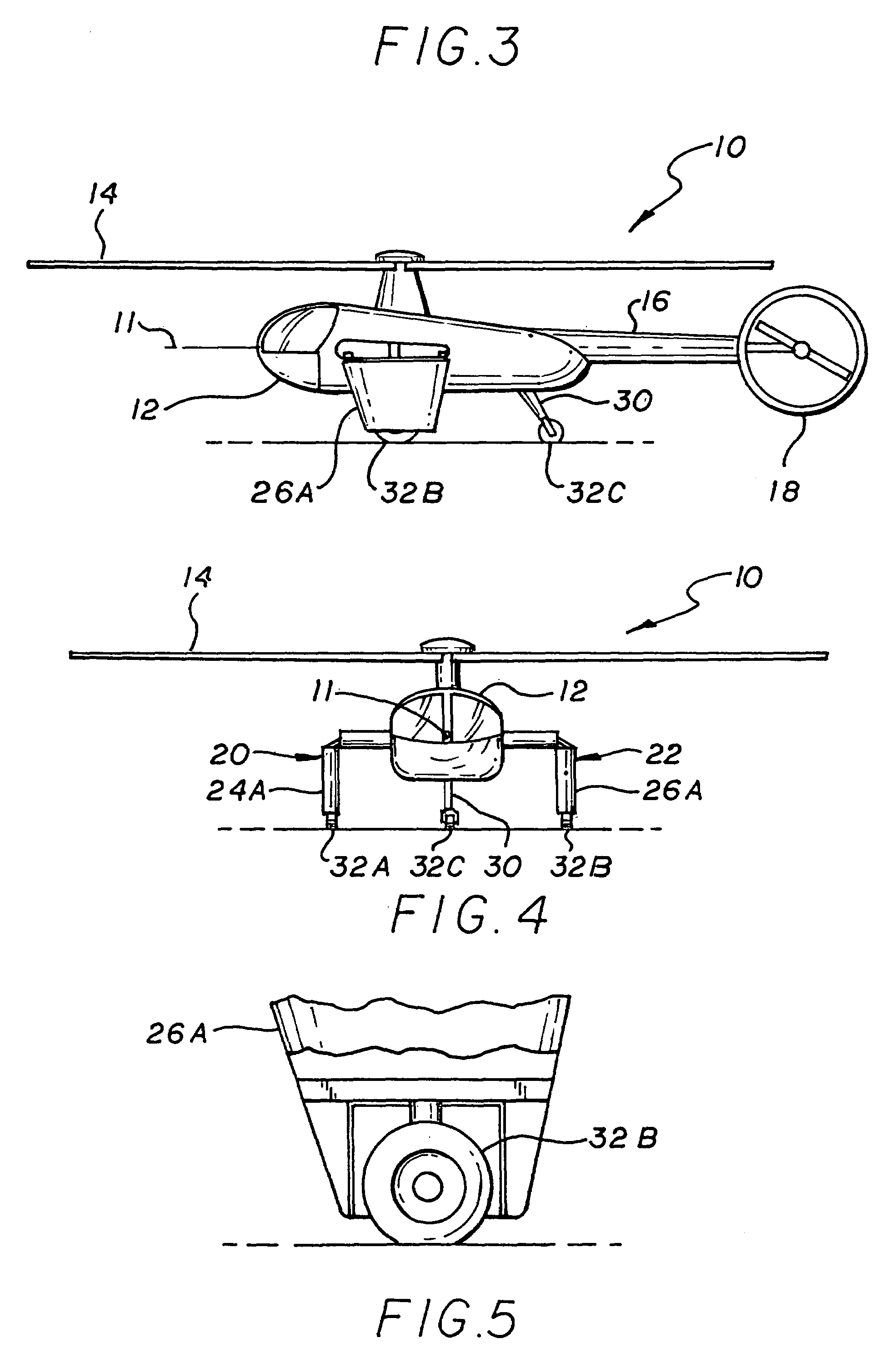
[0017]Referring to FIGS. 1 and 2, a helicopter, generally indicated by numeral 10, having longitudinal axis 11. The helicopter 10 includes a fuselage 12 having a main rotor 14, tail boom 16 incorporating a tail rotor 18. This particular configuration is presented for purposes of illustration only; other configurations are adaptable. Right and left wings 20 and 22 are mounted to the fuselage 12. The wings 20 and 22 have portions 24 and 26 movable from a horizontal position as shown in FIG. 1 to a vertically downward position indicated by numerals 24A and 26B shown in FIG. 2. It should be noted that the portions 24 and 26 of the wings can include the whole wings or any portion thereof as long as they extend beyond the fuselage 12 when in the vertical position. Note also they need not extend totally vertical as indicated in FIG. 3, again as long as they extend beyond the fuselage 12.

[0018]Thus when the wings 20 and 22 have the portions 24 and 26 in the horizontal position they provide ...


PUM


Abstract

The invention is a helicopter that includes a fuselage with a longitudinal axis, a main rotor and tail rotor; and right and left wings mounted to said fuselage. The right and left wings having at least a portion of which are rotatable from a horizontal position wherein they produce lift in forward flight, to an at least partially downward position wherein they act as landing struts.

Description

BACKGROUND OF THE INVENTION[0001]1. Field of the Invention[0002]The invention relates to the field of aircraft and, in particular, to a helicopter design.[0003]2. Description of Related Art[0004]Compound helicopters, having wings to provide lift during horizontal flight, loose efficiency during hover because of the disruption of downwash from the main rotor. This problem was addressed in U.S. Pat. No. 2,580,312 “Convertible Airplane And Helicopter” by H. K. Moore. Moore discloses an aircraft having a pusher propeller as well as a rotor. The wings of the airplane can be rotated from their leading edge downward, thus minimizing the effect of rotor downwash during vertical descent. However separate landing gear is required. Another approach is disclosed in U.S. Pat. No. 2,881,898 “Air Vehicle With Rotary Wing. By A. Flettner. Flettner discloses a compound helicopter type where in the wing tips of the wing are rotated downward by downwash of main rotor. During horizontal flight the lift...

Claims


Application Information

Patent Timeline
Patent Type & Authority Patents(United States)
IPC IPC(8): B64C27/26
CPCB64C27/26B64C2025/325
Inventor ARATA, ALLEN A.
Owner NORTHROP GRUMMAN SYST CORP
Why Eureka
Try Eureka