
Section bar connection device and section bar apparatus with the same

A connecting device and profile technology, which is applied in the connection of rods, connecting components, mechanical equipment, etc., can solve the problems of damaging the appearance, insufficient connection, and small force bearing area of ​​screws or pull rivets, etc., to increase the force bearing area , The connection is firm and the effect of ensuring the tensile strength

Inactive Publication Date: 2009-08-05
深圳市迪威司国奥家具有限公司
View PDF0 Cites 14 Cited by
  • Summary
  • Abstract
  • Description
  • Claims
  • Application Information

AI Technical Summary

Problems solved by technology

[0002] At present, most of the common profile connection methods on the market use L-shaped right-angled connection. The advantage of this connection method is that the installation speed is fast, but because one of the L-codes must be exposed outside, it destroys the overall appearance. The connecting parts are fastened by the straight connection between the self-tapping screw and the connecting code. Due to the small stress area of ​​the screw or pull nail, the pulling strength is not enough, so the connection is not firm enough.
Another type of connection is the built-in U-code. This connection method is also connected to the profile with screws or pull nails. The defect is still that the pulling strength is insufficient, and the vertical and horizontal profiles are not connected firmly enough.

Method used


Image

  • Section bar connection device and section bar apparatus with the same
  • Section bar connection device and section bar apparatus with the same
  • Section bar connection device and section bar apparatus with the same

Examples


Embodiment Construction

[0013] In order to make the technical problems, technical solutions and beneficial effects to be solved by the present invention clearer, the present invention will be further described in detail below in conjunction with the accompanying drawings and embodiments. It should be understood that the specific embodiments described here are only used to explain the present invention, not to limit the present invention.

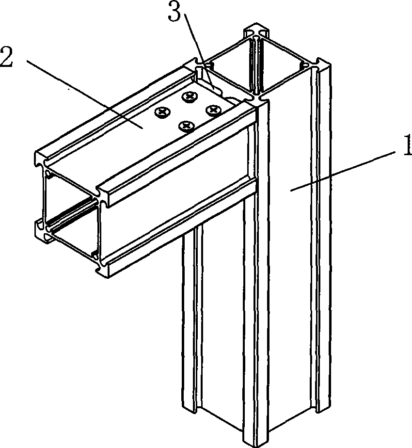
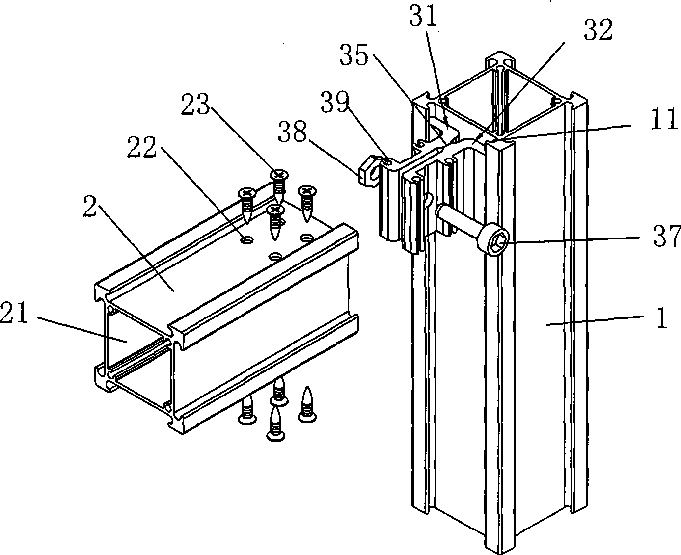
[0014] like figure 1 and figure 2 As shown, the embodiment of the present invention provides a profile device, including a first profile 1 , a second profile 2 and a profile connecting device 3 for connecting the first and second profiles 1 , 2 .

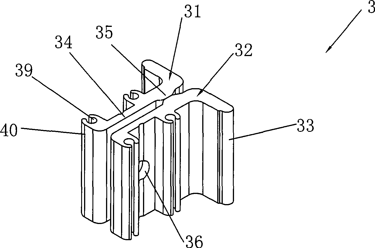
[0015] Please refer to image 3 and Figure 4 , the profile connection device 3 includes a left wing 31 and a right wing 32, and the left and right wings 31, 32 each have a connecting portion 33 and an opposite portion 34 connected to the first profile piece 1 and the second profile piece 2, respectively. There are ...


PUM


Abstract

The invention provides a profile connecting device and a profile device with the profile connecting device. The profile device comprises a first profile piece, a second profile piece and the profile connecting device connecting the first profile piece and the second profile piece; the profile connecting device comprises a left wing and a right wing which are provided with corresponding parts and connecting parts respectively connected with the first profile piece and the second profile piece; the corresponding parts are oppositely arranged, and the corresponding positions of the sides of the corresponding parts are provided with lug bosses mutually abutted; and each connecting part is connected with each corresponding part and positioned at one side of each lug boss, and the other side of the lug boss on the corresponding part is connected with a force application piece applying pressure to the corresponding part. The corresponding parts use the lug boss as the fulcrum after being pressed, the connecting parts press the first profile piece by utilizing the lever principle, profile connecting device is connected with the first profile piece by the connecting part on the profile connecting device, so that the stress area is increased, the tensile strength is ensured, and the firm connection between profiles is realized.

Description

technical field [0001] The invention relates to a profile connecting device and profile equipment using the profile connecting device. Background technique [0002] At present, most of the common profile connection methods on the market use L-shaped right-angled connection. The advantage of this connection method is that the installation speed is fast, but because one of the L-codes must be exposed outside, it destroys the overall appearance. The connecting parts are fastened by the straight connection between the self-tapping screw and the connecting code. Since the stress area of ​​the screw or pull nail is small, its pulling strength is insufficient, so that the connection is not firm enough. Another type of connection is the built-in U-code. This connection is also connected vertically with the profile with screws or pull rivets. Its defect is still that the pulling strength is insufficient, and the vertical and horizontal profiles are not firmly connected. Contents of...

Claims


Application Information

Patent Timeline
IPC IPC(8): F16S3/04
CPCF16B7/187F16B7/0473
Inventor 刘易辉
Owner 深圳市迪威司国奥家具有限公司
Learn More