Connector easily enabling electrical inspection of contacts

a technology of electrical inspection and connector, applied in the direction of coupling contact members, coupling device connections, coupling/disassembly of coupling parts, etc., can solve the problems of difficult to deal with a connector having contacts, impede the operation of electromagnetic shielding of the cover, and difficult to inspect contacts. , to achieve the effect of easy enabling electrical inspection of contacts

Active Publication Date: 2006-11-28
JAPAN AVIATION ELECTRONICS IND LTD
View PDF5 Cites 7 Cited by
  • Summary
  • Abstract
  • Description
  • Claims
  • Application Information

AI Technical Summary

Benefits of technology

[0009]It is therefore an object of this invention to provide a connector that easily enables electrical inspection of contacts without adversely affecting the electromagnetic shielding operation of a cover.
[0010]It is another object of this invention to provide a connector that easily enables electrical inspection of contacts even when the contacts are arranged at a narrow pitch.

Problems solved by technology

However, since the small holes are formed so as to be arranged in the row, each hole is limited to a small size and therefore the electrical inspection of the contacts is not easy.
Particularly, it is difficult to deal with a connector having contacts that are arranged at a narrow pitch.
However, since the elongated holes formed in the cover are each large in size, the electromagnetic shielding operation of the cover is largely impeded.

Method used


Image

  • Connector easily enabling electrical inspection of contacts
  • Connector easily enabling electrical inspection of contacts
  • Connector easily enabling electrical inspection of contacts

Examples


Embodiment Construction

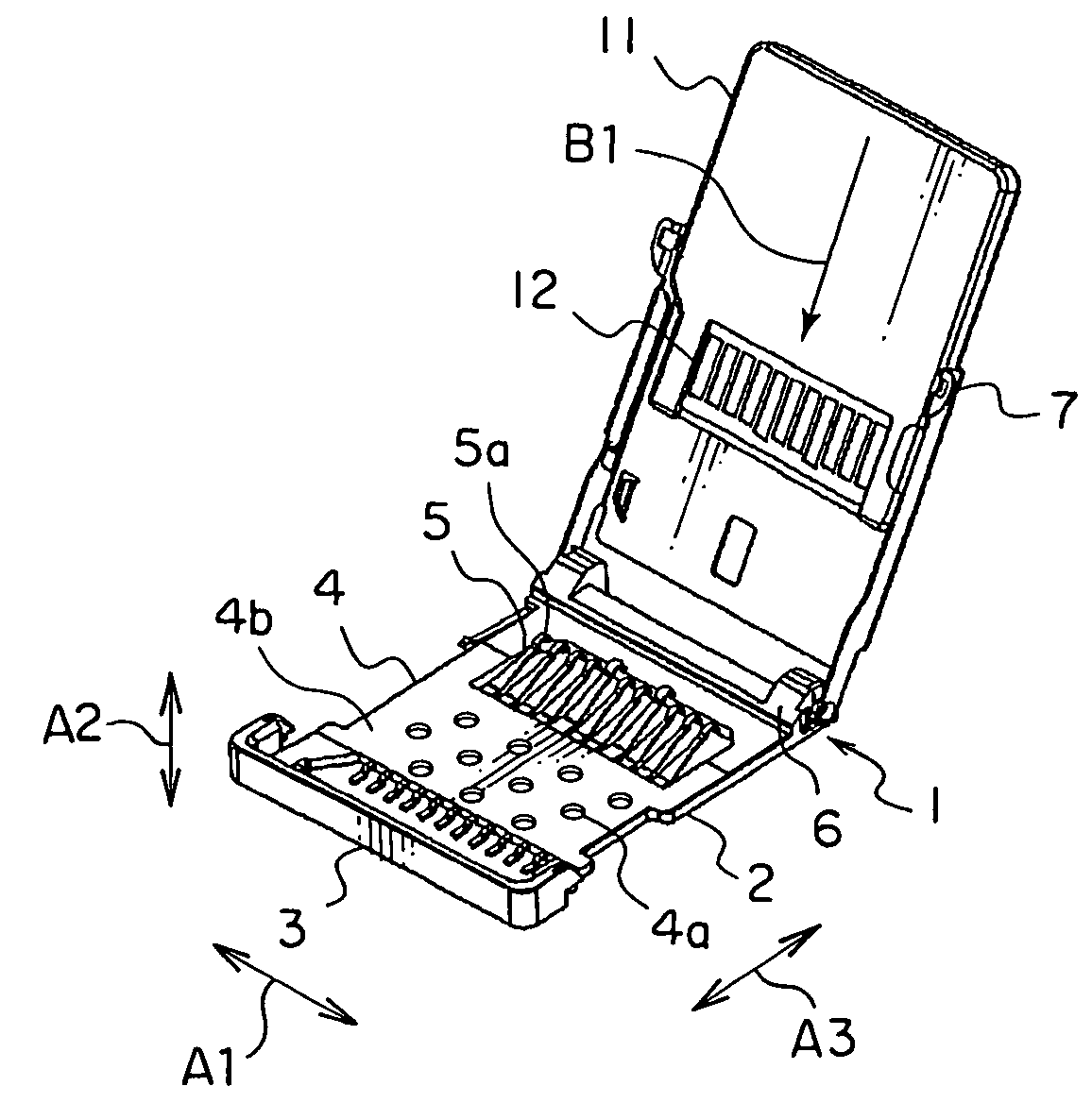
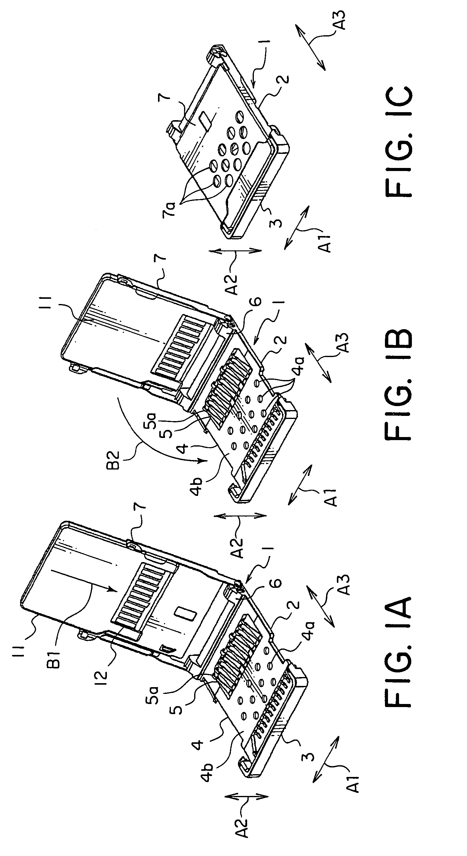
[0026]Referring to FIGS. 1A and 1B, description will be made about an outline of a connector according to an embodiment of this invention.

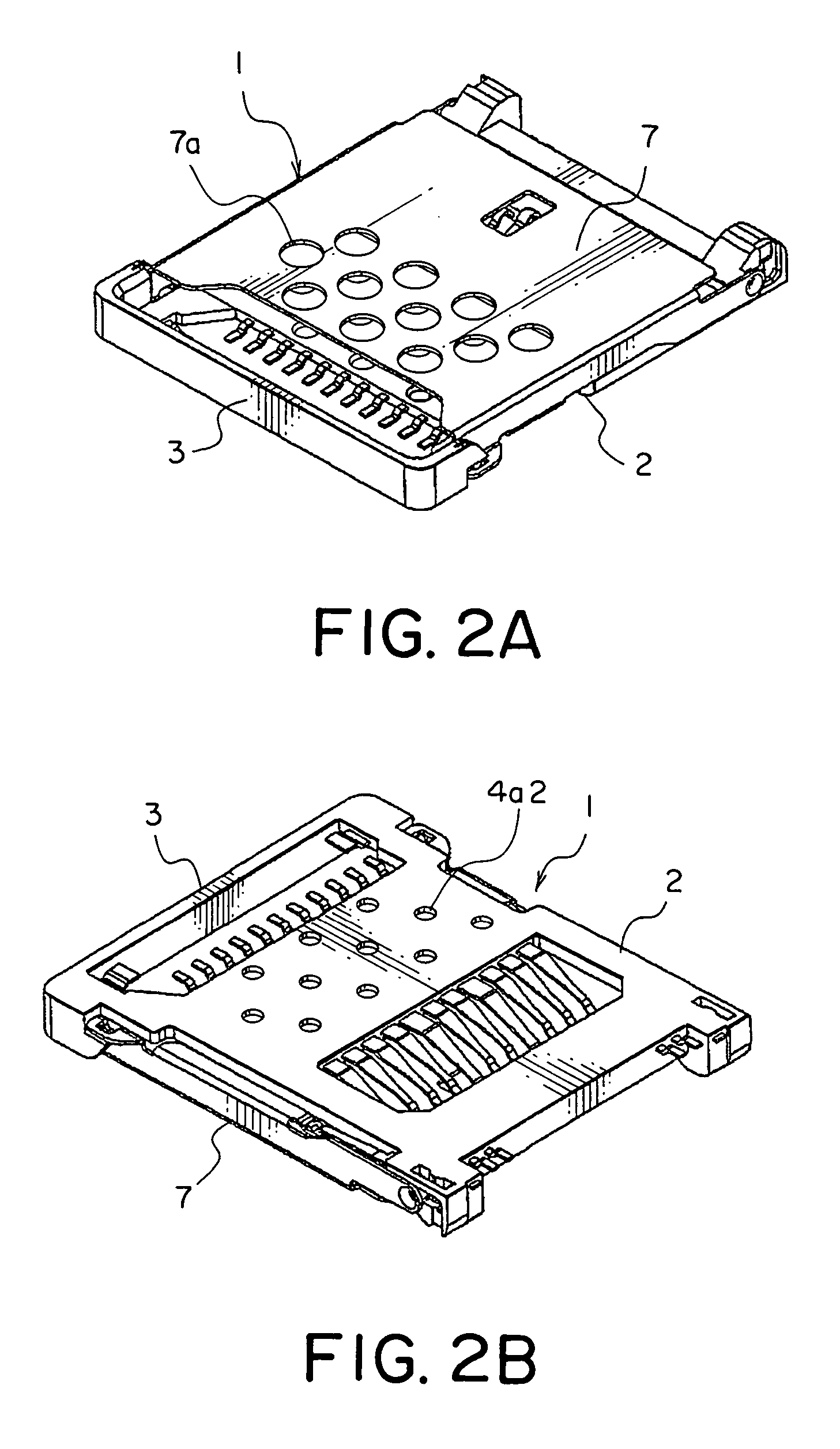
[0027]The shown connector 1 is adapted for connection of an IC card 11, i.e. a connection object, and comprises a connector body 2. The connector body 2 comprises a frame 3 and a flat-plate insulator 4 provided in the frame 3. The insulator 4 retains eleven conductive contacts 5 arranged in a row in a first direction A1 at a constant pitch.

[0028]Inspection hole portions 4a are formed through the insulator 4 at eleven portions thereof in one-to-one correspondence with the contacts 5. The inspection hole portions 4a are arranged so as to be divided into three rows in a third direction A3 perpendicular to the first direction A1 and a second direction A2. Therefore, the inspection hole portions 4a that are adjacent to each other in the first direction A1 are offset in position from each other in the third direction A3.

[0029]Each contact 5 has a contac...


PUM


Abstract

In a connector for connection to a connection object, a plurality of contacts are arranged in a first direction in the connector body and comprises contact portions and retaining portions, respectively. Each of the contact portions is adapted to be connected to the connection object. The connector body retains the retaining portions. A cover is coupled to the connector body and adapted to push the connection object toward the contact portions in a second direction perpendicular to the first direction. The retaining portions have inspection exposure portions at positions, respectively, that face the cover in the second direction. Adjacent ones in the first direction of the inspection exposure portions are offset in position from each other in a third direction perpendicular to the first and second directions.

Description

[0001]This application claims priority to prior Japanese patent application JP2004-285992, the disclosure of which is incorporated herein by reference.BACKGROUND OF THE INVENTION[0002]This invention relates to a connector for connecting a connection object such as an IC card and, in particular, relates to a connector that enables electrical inspection of contacts.[0003]One example of a connector of this type is disclosed in JP-A-2004-146166. In the disclosed connector, seven contacts are arranged in a row and retained in a resin housing. The housing is formed with seven circular small holes arranged in a row so as to correspond to the contacts, respectively.[0004]According to this structure, continuity of each contact can be checked by contacting a probe pin with the corresponding contact through the corresponding small hole.[0005]However, since the small holes are formed so as to be arranged in the row, each hole is limited to a small size and therefore the electrical inspection of...

Claims


Application Information

Patent Timeline
Patent Type & Authority Patents(United States)
IPC IPC(8): H01R13/62
CPCH01R12/83H01R13/24Y10S439/912
Inventor MATSUNAGA, AKIHIRO
Owner JAPAN AVIATION ELECTRONICS IND LTD
Why Eureka
Try Eureka