Calibration system for a spectral luminometer and a method for calibrating a spectral luminometer

a spectral luminometer and calibration system technology, applied in the direction of optical radiation measurement, instruments, spectrometry/spectrophotometry/monochromators, etc., can solve the problems of wavelength error, sensitivity error, and inability to avoid wavelength error and sensitivity error resulting from over-the-time change or thermal chang

Active Publication Date: 2006-12-19
KONICA MINOLTA SENSING INC
View PDF8 Cites 30 Cited by
  • Summary
  • Abstract
  • Description
  • Claims
  • Application Information

AI Technical Summary

Benefits of technology

[0009]It is another object of the present invention to provide a spectral luminometer calibration system and calibration method which enable a user to calibrate the wavelength and sensitivity of the spectral luminometer.

Problems solved by technology

As shown in FIG. 18, a relative position change of optical elements of the polychrometer directly and sharply leads to a wavelength error.
Further, a sensitivity error is caused by a property change of an optical element such as a reflection efficiency of the diffraction grating 313 and a circuit construction.
This is also caused by the aforementioned wavelength error.
Accordingly, occurrences of the wavelength error and the sensitivity error resulting from an over-the-time change or a thermal change are unavoidable and a recalibration is essential to maintain precision.
However, the recalibration to maintain the precision of the spectral luminometer requires the same facility and operation as the calibration at the time of production and, therefore, has been difficult to be done at a user side.
Such a recalibration made by sending the spectral luminometer back takes cost and time both at the producer side and at the user side and is difficult to do with a sufficient frequency.
Further, in the case that a spare spectral luminometer is necessary as a substitution while the spectral luminometer is at the factory for the recalibration, and a cost therefor is also necessary.

Method used


Image

  • Calibration system for a spectral luminometer and a method for calibrating a spectral luminometer
  • Calibration system for a spectral luminometer and a method for calibrating a spectral luminometer
  • Calibration system for a spectral luminometer and a method for calibrating a spectral luminometer

Examples


second embodiment

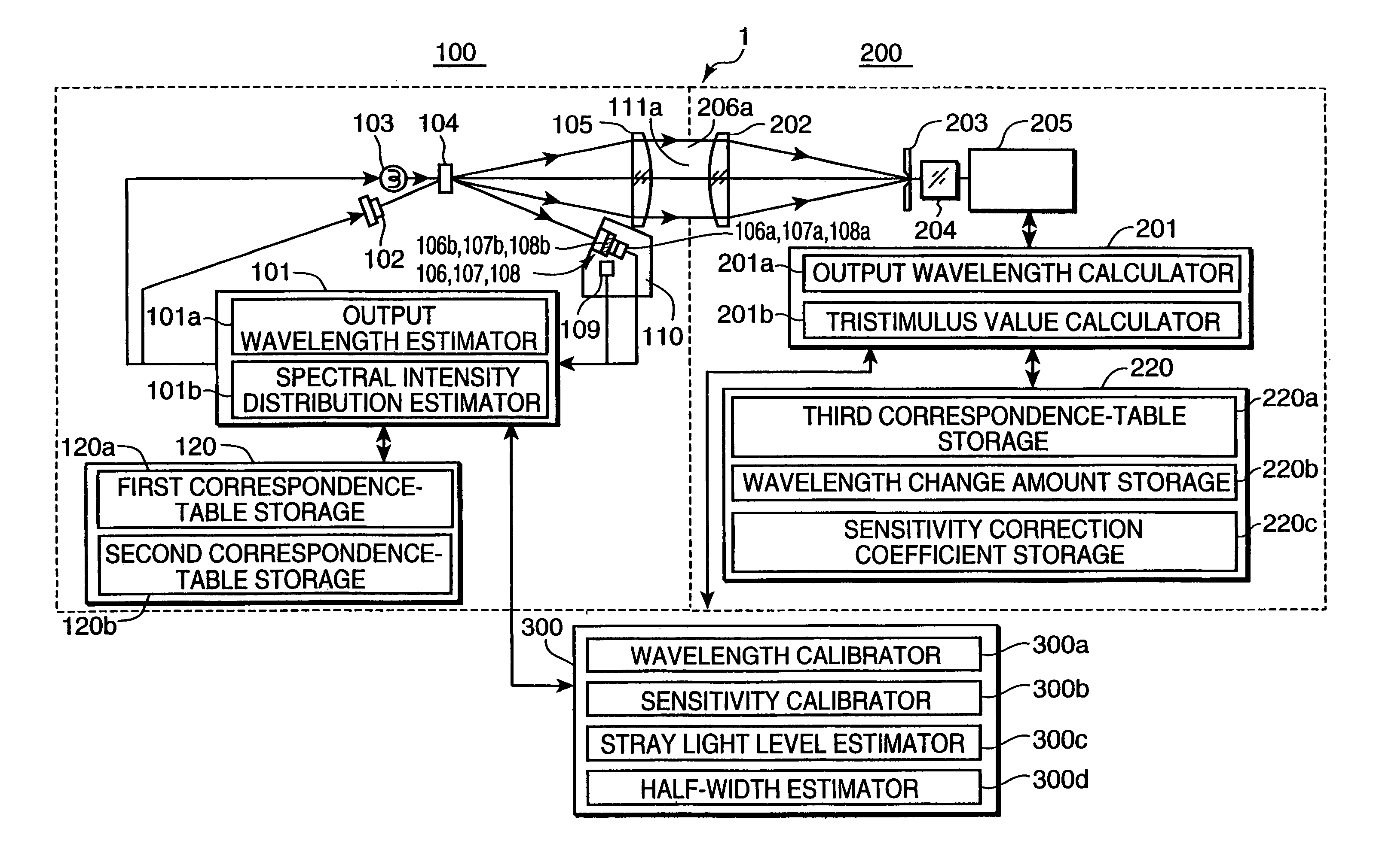
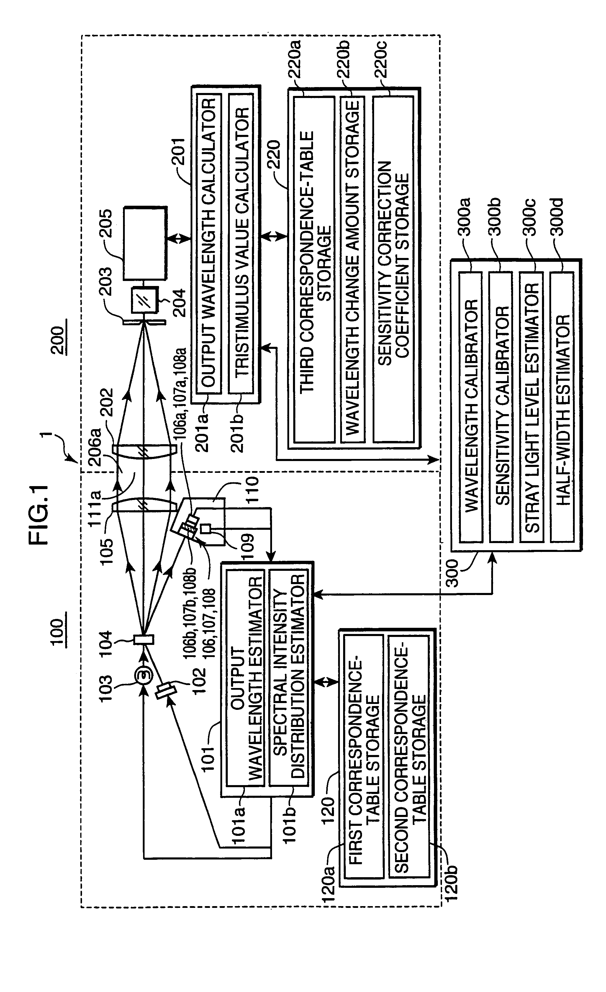
[0167]FIG. 12 is a diagram showing a construction of a calibration light source of the second embodiment near an emission-line light source and an incandescent light source. As shown in FIG. 12, a calibration light source 100 of this embodiment is provided with an emission-line light source 102′, an incandescent light source 103 and a diffusing plate 104. The emission-line light source 102′ includes a three-wavelength type fluorescent lamp 112 and a band pass filter 113.

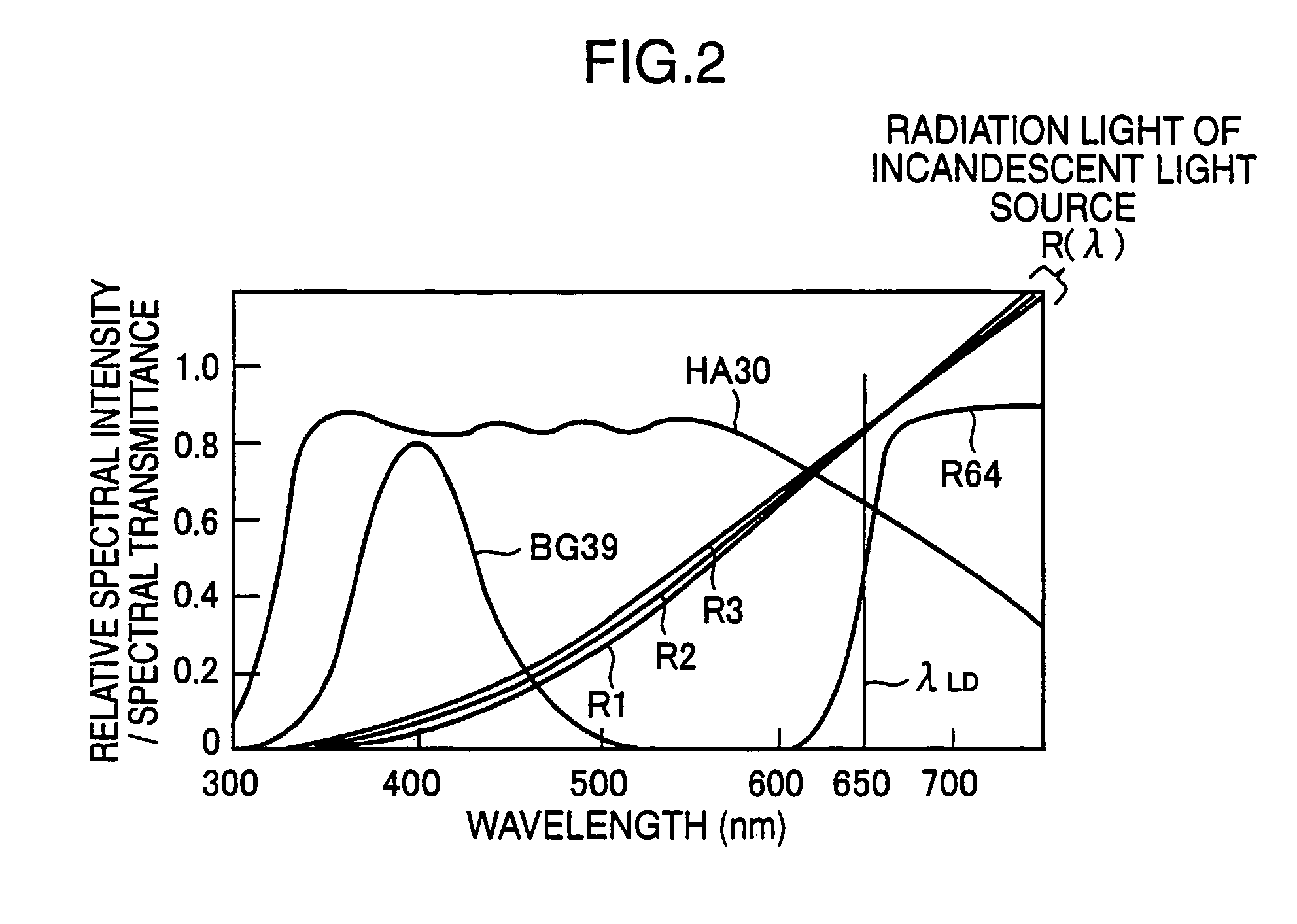
[0168]FIG. 13 is a graph showing spectra when the three-wavelength type fluorescent lamp is used as an emission-line light source, wherein vertical axis represents relative spectral intensity and transmittance and horizontal axis represents wavelength.

[0169]As shown in FIG. 13, the three-wavelength type fluorescent lamp radiates strong emission lines GL near 546 nm. Since there are emission lines or fluorescent radiation in the other wavelength ranges, light emissions in the other wavelength ranges can be suppressed ...

first embodiment

[0170]Since the wavelength of the emission lines GL results from an energy level of mercury atoms which are a fluorescent material of the fluorescent lamp, it is constantly stable free from an individual difference, a temperature dependence and a change over time. Accordingly, it is not necessary to monitor the emission-line wavelength unlike the first embodiment in which the visible LD is used as an emission-line light source and to consider the respective correspondence tables, relating the emission-line wavelength and the output ratios of the light receiving sensors of the light receiving unit at wavelengths near the emission-line wavelength, stored in the spectral luminometer 200, and the individual differences of the output wavelengths. It is sufficient to store only a correspondence table of about three emission-line wavelengths of 545 nm, 546 nm and 547 nm and output ratios of the light receiving sensors, whereby a time required to set the correspondence table in the spectral...


PUM


Abstract

A calibration light source outputs emission lines having a known emission-line wavelength, a spectral luminometer to be calibrated measures an emission-line output of the calibration light source, and a system control unit calibrates the wavelength of the spectral luminometer by estimating the wavelength of the emission-line output from ratios of outputs of a light receiving unit at a plurality of measurement wavelengths neighboring an emission-line wavelength and estimating a wavelength change amount from a difference between the estimated wavelength of the emission-line output and the known emission-line wavelength. The wavelength and the sensitivity of a spectral luminometer can be calibrated at a user side.

Description

[0001]This application is based on patent application No. 2003-201726 filed in Japan, the contents of which are hereby incorporated by references.BACKGROUND OF THE INVENTION[0002]This invention relates to a calibration system for a spectral luminometer for measuring and evaluating luminances and colors of various light sources and display devices and particularly to a calibration system for a spectral luminometer for a wavelength calibration and a spectral sensitivity calibration, and a method for calibrating a spectral luminometer.[0003]Spectral luminometers for measuring and evaluating spectral luminances, luminances and colors of various light sources and display devices have been conventionally widely used (for example, see Japanese Unexamined Patent Publication No. H6-74823). FIG. 18 is a diagram showing a construction of a light splitting unit in a prior art spectral luminometer. As shown in FIG. 18, a light splitting unit 310 built in the prior art spectral luminometer is the...

Claims


Application Information

Patent Timeline
Patent Type & Authority Patents(United States)
IPC IPC(8): G01J3/00G01J3/18G01J3/02G01J3/10G01J3/28
CPCG01J3/10G01J2003/2866
Inventor IMURA, KENJI
Owner KONICA MINOLTA SENSING INC
Why Eureka
Try Eureka