Positioning tool with valved fluid diversion path and method

a technology of fluid diversion path and positioning tool, which is applied in the direction of fluid removal, borehole/well accessories, construction, etc., can solve the problem of possible loss of fluid

Inactive Publication Date: 2006-12-26
HALLIBURTON ENERGY SERVICES INC
View PDF3 Cites 39 Cited by
  • Summary
  • Abstract
  • Description
  • Claims
  • Application Information

AI Technical Summary

Problems solved by technology

After the filter cake is removed, fluid losses may be a problem.

Method used


Image

  • Positioning tool with valved fluid diversion path and method
  • Positioning tool with valved fluid diversion path and method
  • Positioning tool with valved fluid diversion path and method

Examples


Embodiment Construction

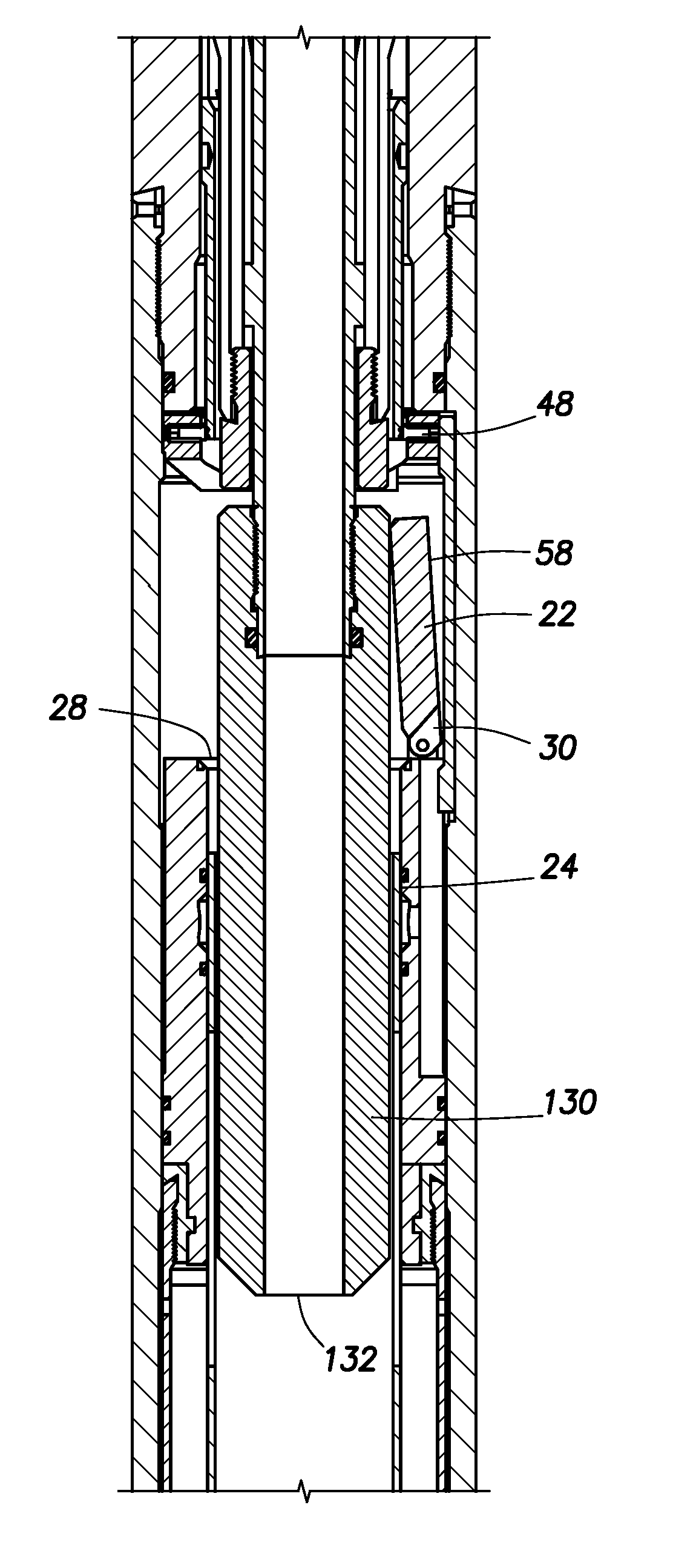
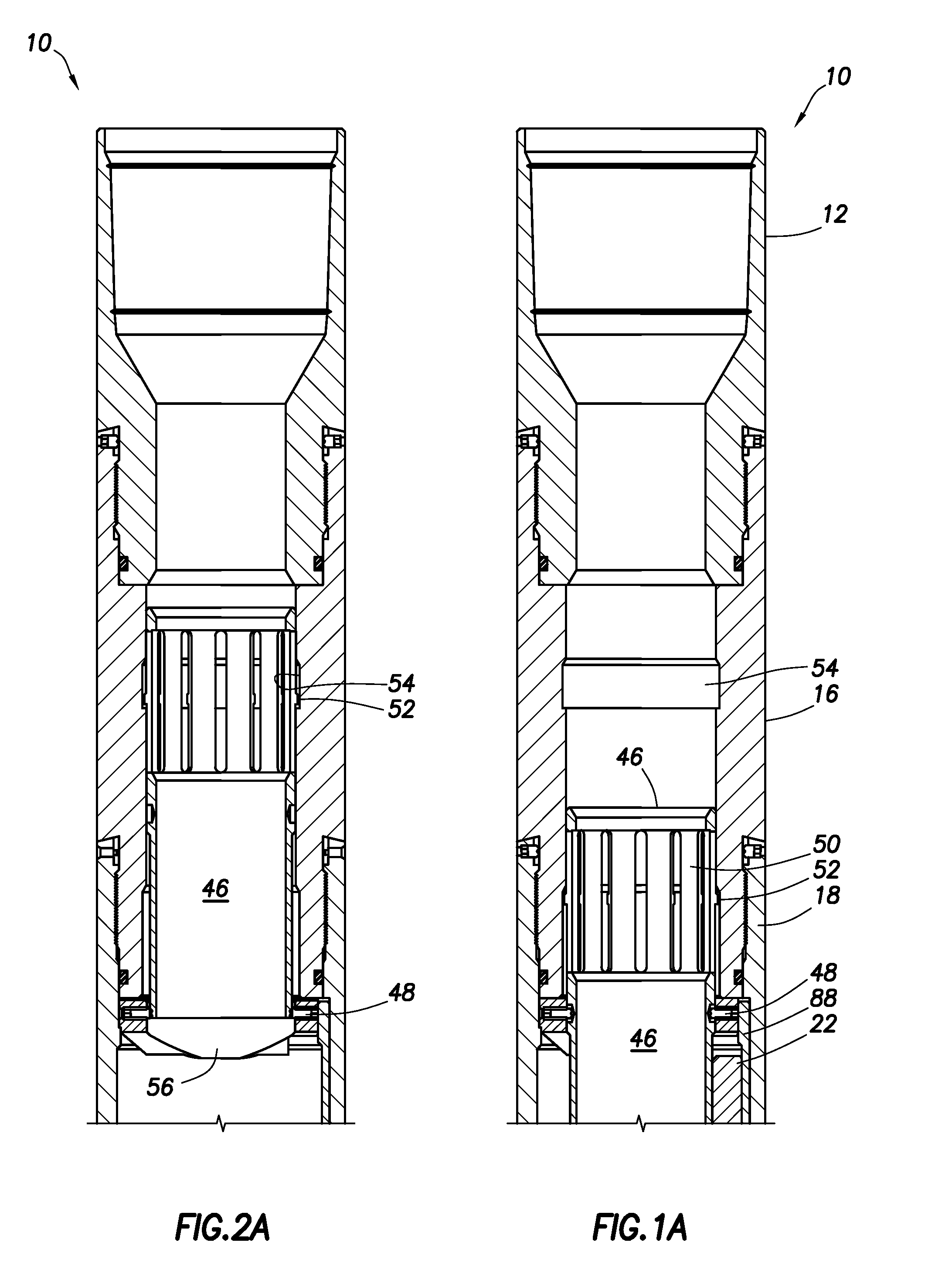
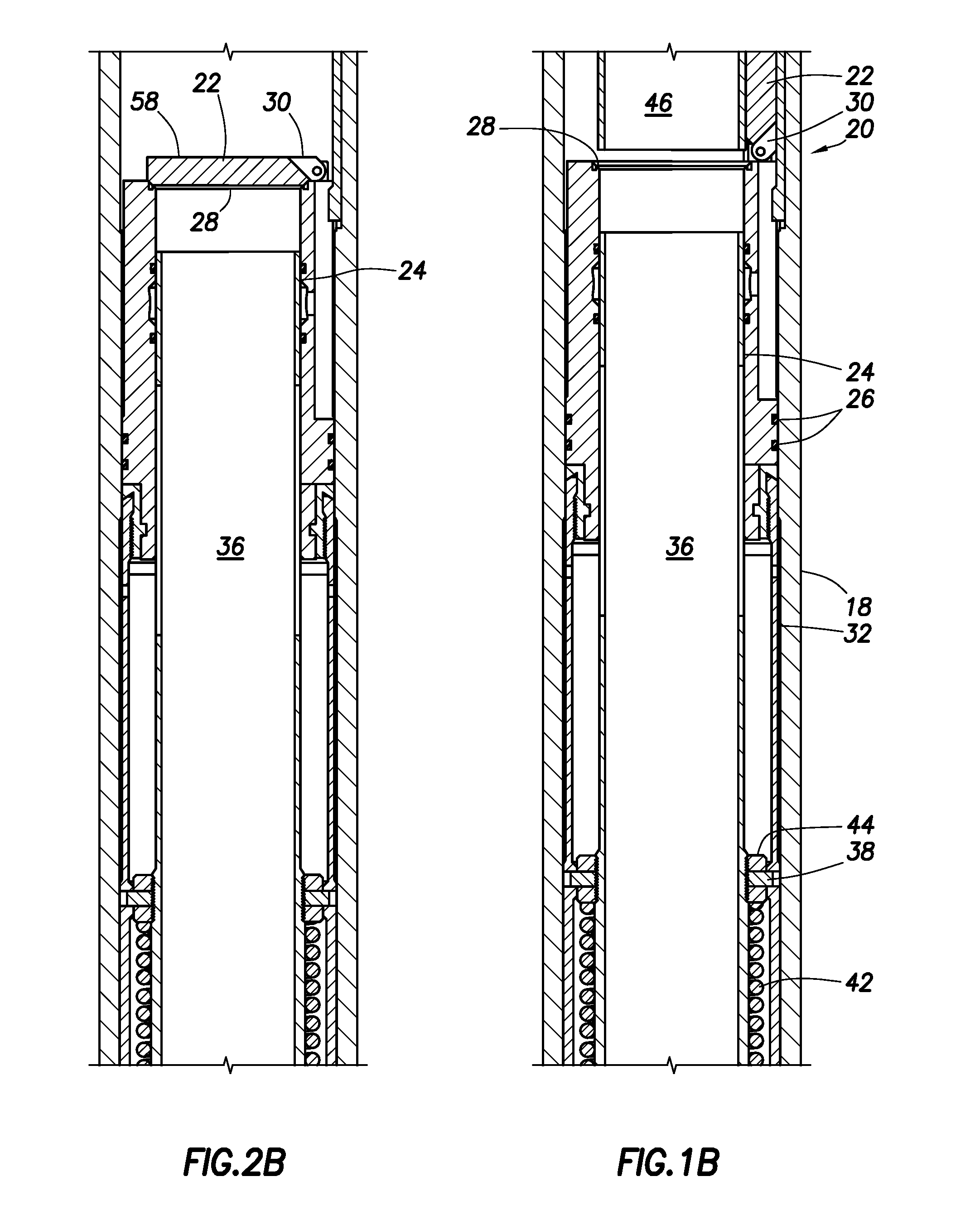
[0026]In describing the embodiments of the present invention, various elements are referred to by their normal relative positions when used in an oil well. The terms above or up hole mean that an element is closer to the surface location of a well. The terms below or down hole mean that an element is closer to the end of the well farthest from the surface location. In deviated or horizontal wells, the various elements may actually be at the same vertical elevation. Such terms are not meant to limit the orientation in which a device may be operated in a well, but only to help understand the relative positions of elements that make up the device.

[0027]In describing a flapper valve, i.e. a flapper and valve seat, references are made to pressures relative to the flapper. The terms pressure from below and pressure from below to above mean that the pressure below the flapper is greater than the pressure above the flapper. The terms pressure from above and pressure from above to below mean...


PUM


Abstract

A positioning tool for moving an element in a flow path of a down hole system without actuating a pressure actuated device in the system. The positioning device includes a choke for restricting flow of fluid between the positioning device and the down hole system, a flow diversion path from the upper end of the positioning device to a lower end of the positioning device, and a valve allowing fluid to flow through the diversion path when the choke is proximate the pressure actuated device and blocking flow of through the diversion path when the choke is displaced from the pressure actuated device. The down hole system may be a flapper type fluid loss device with a pressure actuated opening prop.

Description

CROSS-REFERENCE TO RELATED APPLICATIONS[0001]This application is related to U.S. patent application Ser. No. 11 / 048,585, entitled “Bi-directional Fluid Loss Device”, filed on even date herewith and hereby incorporated by reference for all purposes.STATEMENT REGARDING FEDERALLY SPONSORED RESEARCH OR DEVELOPMENT[0002]Not applicable.REFERENCE TO A MICROFICHE APPENDIX[0003]Not applicable.FIELD OF THE INVENTION[0004]The present invention relates to positioning devices for use in oil wells, and more particularly to a positioning tool that may be used in a down hole system without accidentally actuating a pressure actuated device in the system.BACKGROUND OF THE INVENTION[0005]Oil wells are drilled from the surface of the earth down to and through hydrocarbon bearing formations to allow recovery of the hydrocarbons through the well. The wells are often cased down to the producing formation. The well may be cased or lined with a metal liner through the producing formation or may be left in o...

Claims


Application Information

Patent Timeline
Patent Type & Authority Patents(United States)
IPC IPC(8): E21B34/14
CPCE21B34/10E21B34/14E21B43/04E21B43/045E21B2034/005E21B2200/05
Inventor RICHARDS, W. MARK
Owner HALLIBURTON ENERGY SERVICES INC
Why Eureka
Try Eureka