Vehicle seat comprising a backrest that can be folded down forwards

a backrest and vehicle seat technology, applied in the field of vehicle seats comprising backrests, can solve the problems of confusion, risk of damage to the mechanism articulating and pivoting the backrest with respect, etc., and achieve the effect of reducing the drawback

Inactive Publication Date: 2006-12-26
FAURECIA
View PDF14 Cites 52 Cited by
  • Summary
  • Abstract
  • Description
  • Claims
  • Application Information

AI Technical Summary

Benefits of technology

[0012]By virtue of these arrangements, the seat remains simple because the user actuates at least two different control members to control the various positions of the backrest with respect to the cushion. Each control member activates at most two of the aforementioned three functions and this limits the risk of confusion with regard to the adjustment that is to be made, and the risk of damage to the mechanisms articulating and pivoting the backrest with respect to the cushion should the user force the single control member having not managed to obtain the expected backrest movement.
[0020]the lever is able to hold the blocking member in its active position, when the backrest is in its intermediate folded-down position;
[0031]the lever is able to hold the blocking member in its active position when the backrest is in its intermediate folded-down position;
[0054]the lever comprises guide means designed so that the lever is driven, towards its active position in which it causes the unlocking of the slide rails, in the rotation of the backrest from a comfort position towards the intermediate folded-down position so as to prevent the unlocking of the slide rails when the backrest is in the folded-flat position;

Problems solved by technology

Each control member activates at most two of the aforementioned three functions and this limits the risk of confusion with regard to the adjustment that is to be made, and the risk of damage to the mechanisms articulating and pivoting the backrest with respect to the cushion should the user force the single control member having not managed to obtain the expected backrest movement.

Method used


Image

  • Vehicle seat comprising a backrest that can be folded down forwards
  • Vehicle seat comprising a backrest that can be folded down forwards
  • Vehicle seat comprising a backrest that can be folded down forwards

Examples


first embodiment

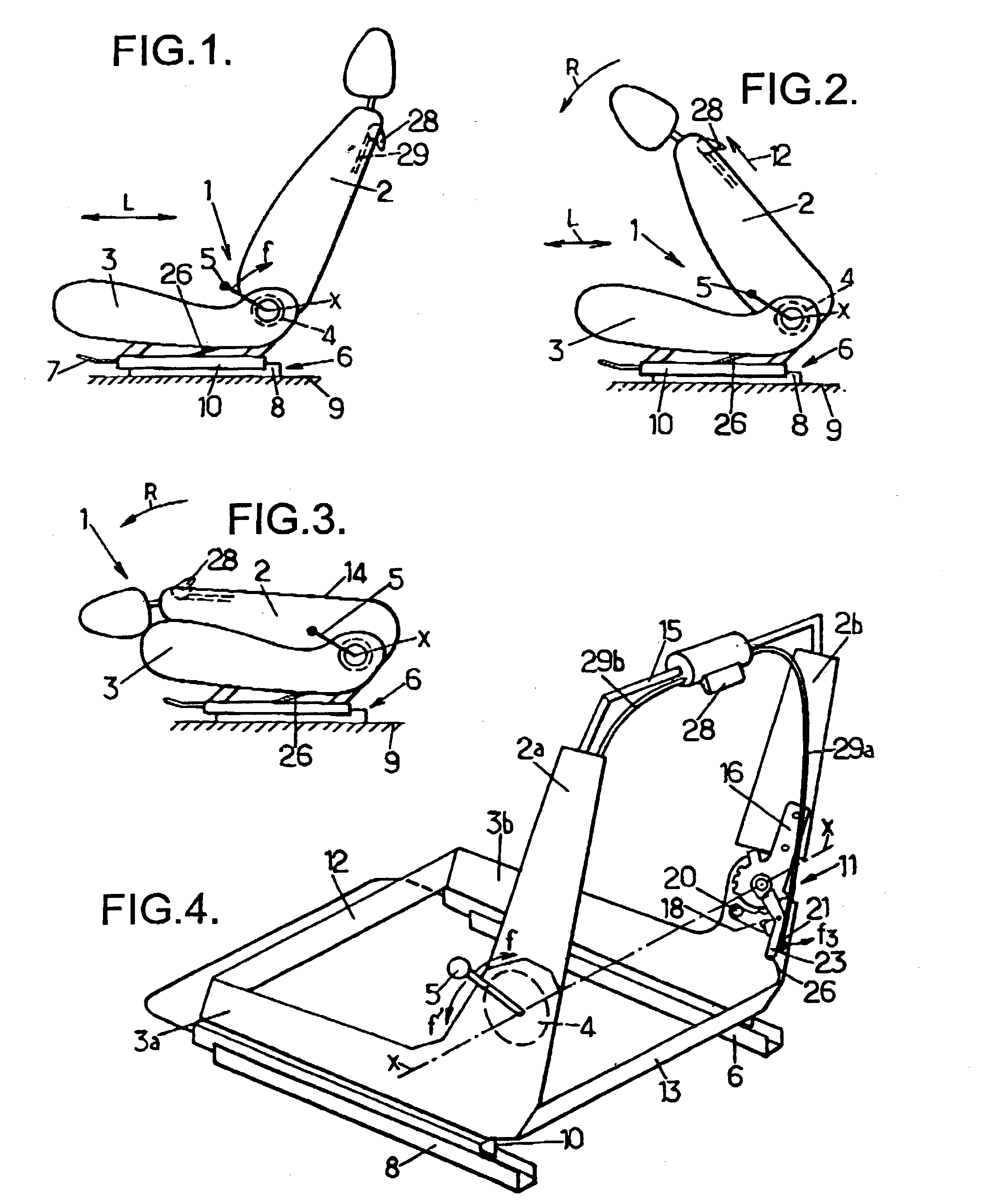
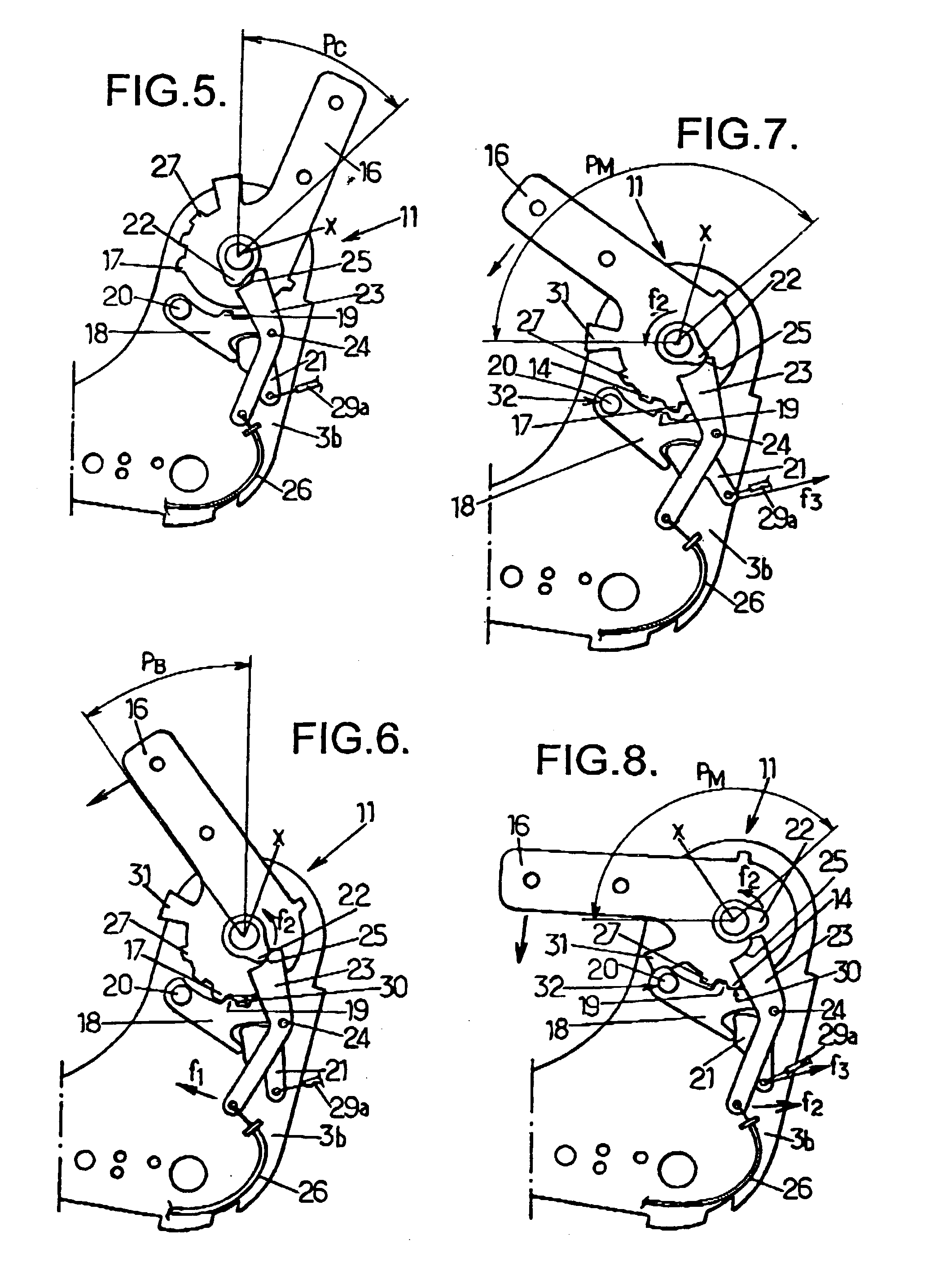
[0092]the seat according to the invention is described hereinbelow in conjunction with FIGS. 4 to 8.

[0093]The tilting of the backrest 2 with respect to the cushion 3 is controlled by a mechanism comprising the articulation 4 situated on one side of the seat 1 and a blocking mechanism 11, situated on the opposite side of the seat 1 to the side on which the articulation 4 is mounted.

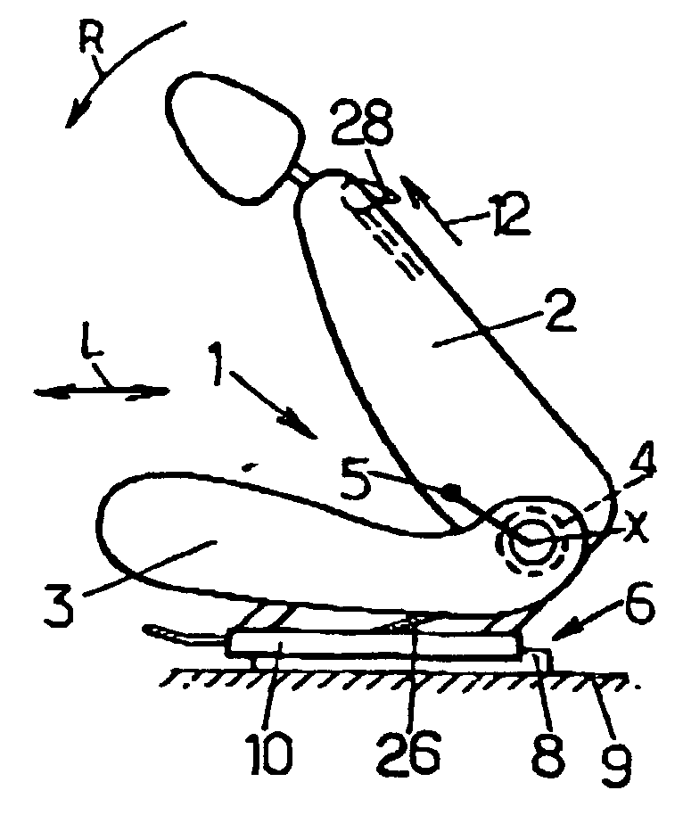
[0094]The control member for activating the function of adjusting the comfort and the control member for activating the function of tipping the backrest 2 into an intermediate folded-down position are coincident and correspond to the handle 5, while the control member for activating the function of tipping the backrest 2 into the folded-flat position is separate and distinct from the previous one and corresponds to a knob 28.

[0095]As depicted in FIG. 4, the main metal skeleton of the cushion 3 comprises two first side flanges 3a, 3b connected together by a front 12 and a rear 13 crosspiece. The first side ...

second embodiment

[0115]The second embodiment is described hereinbelow in greater detail in relation to FIGS. 1 to 3 and 9 to 12.

[0116]The seat 1 corresponding to this second embodiment comprises a backrest 2 mounted to pivot on a cushion 3 about a horizontal pivot axis X, and an articulation 4 controlled by a control member, for example a rotary handle 5 (see FIG. 1).

[0117]The cushion 3 is carried by two slide rails 6 the unlocking of which can be achieved by means of a bar 7.

[0118]The tipping of the backrest 2 with respect to the cushion 3 is controlled by a mechanism comprising an articulation 4 situated on one side of the seat 1 and a blocking mechanism 11 situated on the opposite side of the seat 1 to the articulation 4.

[0119]The control member allowing activation of the function of adjusting comfort, that is to say the handle 5, the control member allowing activation of the function of tipping the backrest into an intermediate folded-down position, that is to say a lever 35, and the control mem...

third embodiment

[0139]The third embodiment is described hereinbelow in greater detail in relation to FIGS. 1 to 3 and 13 to 17.

[0140]The seat 1 corresponding to this third embodiment comprises a backrest 2 mounted to pivot on a cushion 3 about a horizontal pivot axis X, and an articulation 4 controlled by a control member, for example a rotary handle 5 (see FIG. 1).

[0141]The cushion 3 is carried by two slide rails 6 the unlocking of which can be achieved by means of a bar 7.

[0142]The tipping of the backrest 2 with respect to the cushion 3 is controlled by a mechanism comprising an articulation 4 situated on one side of the seat 1 and a blocking mechanism 11 situated on the opposite side of the seat 1 to the articulation 4.

[0143]The control member allowing activation of the function of adjusting comfort and the control member allowing activation of the function of tipping the backrest 2 into the folded-flat position are coincident and correspond to the handle 5, but are distinct from the control mem...


PUM


Abstract

Vehicle seat comprising a cushion and a backrest pivoting with respect to the cushion about a horizontal pivot axis by means of an articulation between a range of erect positions of use, a folded-flat position and an intermediate folded-down position.This seat comprises a first, a second and a third control member connecting the cushion to the backrest, one of the first, second and third control members being distinct from the other two.

Description

FIELD OF THE INVENTION[0001]The present invention relates to vehicle seats comprising a backrest that can be folded down forwards.BACKGROUND OF THE INVENTION[0002]More particularly, the invention relates to a vehicle seat comprising:[0003]a cushion intended to be connected to a floor of the vehicle by slide rails,[0004]a backrest mounted to pivot with respect to the cushion about a single horizontal pivot axis between a folded-flat position in which the backrest runs roughly horizontally parallel to the cushion and a comfort position in which the backrest extends roughly vertically and allows its user to sit in the seat, this comfort position lying in a range extending angularly between a rear erect position and a forward erect position of the backrest,[0005]a mechanism for controlling the pivoting of the backrest with respect to the cushion, and which is designed to perform the three functions consisting in:[0006]commanding the articulation to adjust the backrest into a comfort pos...

Claims


Application Information

Patent Timeline
Patent Type & Authority Patents(United States)
IPC IPC(8): B60N2/02A47C1/023A47C1/024B60N2/12B60N2/20B60N2/235
CPCB60N2/206B60N2/2352B60N2/225
Inventor CHARRAS, FABRICEPIERREY, JEAN-FRANCOISTHEVENOT, GERALDREUBEUZE, YANNSAINT SUPERY, JEAN-GABRIELPANET, DAVIDLARDAIS, EMMANUELLELAURE, XAVIERLEGRAS, CEDRIC
Owner FAURECIA
Why Eureka
Try Eureka