Hand piece for microdermabrasion device

a microdermabrasion and hand piece technology, applied in the field of hand piece used for microdermabrasion devices, can solve the problems of affecting the hygienic effect, the ineffective absorbing of dislodged skin cells into the hole, and the inability to effectively absorb dislodged skin cells from the periphery of the abrasive surface, so as to prevent the hygienic problem and effectively absorb dislodged skin cells during the operation

Inactive Publication Date: 2006-12-26
CHUNG TAE JUN
View PDF2 Cites 46 Cited by
  • Summary
  • Abstract
  • Description
  • Claims
  • Application Information

AI Technical Summary

Benefits of technology

The present invention provides a hand piece for a dermabrasion device with a replaceable dermabrasion tip. This prevents hygienic issues and ensures effective absorption of dislodged skin cells during operation. The hand piece creates vacuum pressure around the dermabrasion tip, allowing all dislodged skin cells to be effectively absorbed in the filter assembly.

Problems solved by technology

The technical problem addressed in this patent is the potential for hygienic issues and infection due to the reuse of a dermabrasion device with an integrally formed abrasive surface. Additionally, the device may not effectively absorb skin cells dislodged from the treatment tip due to reduced vacuum pressure at the periphery of the tip.

Method used


Image

  • Hand piece for microdermabrasion device
  • Hand piece for microdermabrasion device
  • Hand piece for microdermabrasion device

Examples


Embodiment Construction

[0014]Hereinafter, preferred embodiments according to the present invention will be explained in detail with reference to the accompanying drawings. In the accompanying drawings, same reference numerals are used to indicate the corresponding elements.

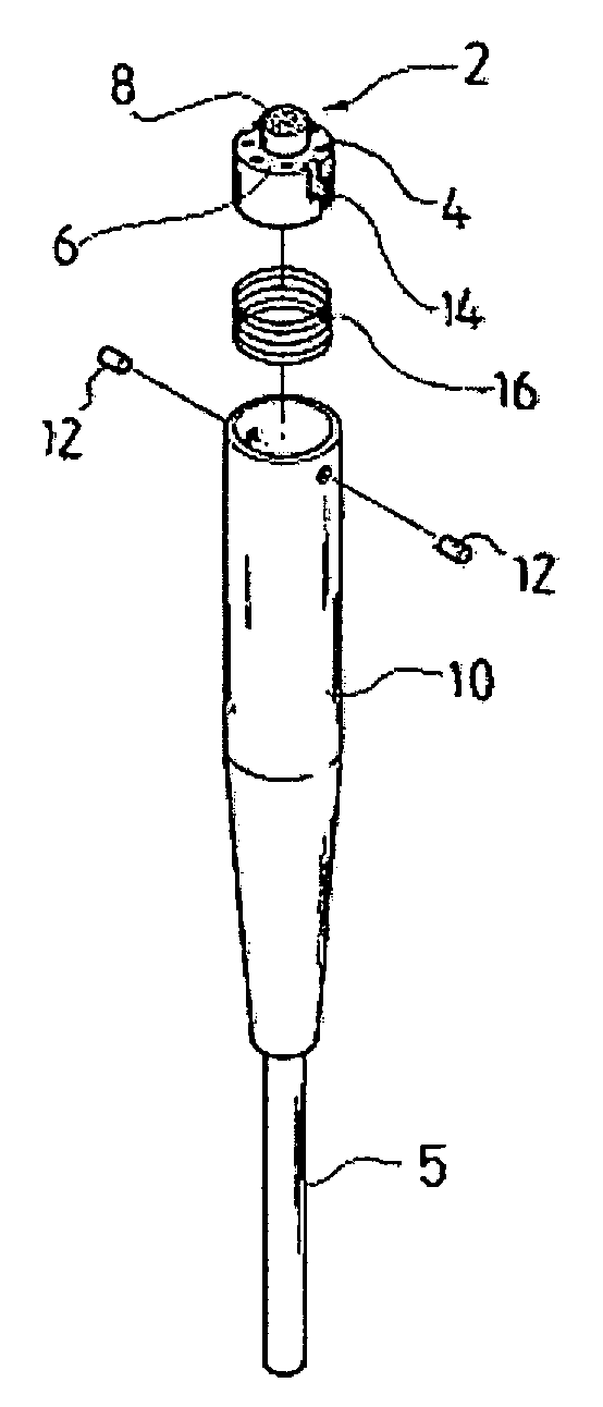
[0015]Referring to FIGS. 3 to 5, the hand piece according to the present invention comprises a housing 10 having a generally tubular shape with a hollow formed therein. The housing is preferably formed with metallic material such as stainless steel. A connecting tube 5 is formed at one end of the housing 10. The connecting tube 5 may be integrally formed with the housing, or may be detachably connected to the housing. Though the connecting tube, vacuum is applied to the inside of the housing connected thereto. Preferably, as shown in the drawings, at least a portion of the housing has a tapered shape to make it easy to grip.

[0016]A spring 16 is inserted into the hollow of the housing 10 and, as shown in FIGS. 4 and 5, one end of the spr...


PUM


Abstract

The present invention relates to a hand piece used for vacuum suction type dermabrasion apparatus. The hand piece includes a replaceable dermabrasion tip installed into a tubular housing. The dermabrasion tip consists of a cylindrical upper stage and a cylindrical lower stage, the upper has a smaller diameter than the lower stage and an abrasive surface formed on the upper surface of the upper stage, and the lower stage has a diameter generally fitting to the diameter of the hollow and a plurality of suction holes are formed through the lower stage around the periphery of the upper stage.

Description


Claims


Application Information

Patent Timeline
Owner CHUNG TAE JUN
Why Eureka
Try Eureka