Shingle assembly with support bracket

a technology of shingle and support bracket, which is applied in the direction of solar thermal energy generation, lighting support devices, candle holders, etc., can solve the problems of shortening the useful life, increasing the probability of water, and reducing the pv electrical outpu

Active Publication Date: 2007-01-02
SUNPOWER CORPORATION
View PDF36 Cites 146 Cited by
  • Summary
  • Abstract
  • Description
  • Claims
  • Application Information

AI Technical Summary

Benefits of technology

[0005]The present invention is directed to a shingle assembly especially useful as a photovoltaic shingle assembly which can be economically mounted directly to a support surface, such as a sloped roof, in a simple manner to create an aesthetically pleasing structure that integrates well with conventional roofing tiles.

Problems solved by technology

Primary among the factors are ease of installation, cost and aesthetics.
However, photovoltaic shingle systems have not been as widely accepted as hoped-for because 1) PV mounted integrally with the building roof as shingles operate at higher temperatures, causing a reduction in PV electrical output due to an inverse relationship between temperature and PV efficiency; 2) the same higher operating temperatures approach or exceed the upper limit of the warranted PV operating temperature (typically 80 degrees C.) and serve to shorten the useful life of the PV shingle; 3) some products call for electrical connections between shingles to be made under the roof deck, requiring holes to be drilled through the roof deck which increases the likelihood of water leaks; 4) there has been poor aesthetic match of PV shingles in conjunction with the non-PV areas of the roof; 5) some PV shingles have been limited to amorphous silicon PV technology, which suffer from a low operating efficiency; and 6) the value of the PV shingle has typically been limited to the electrical output of the PV plus the material value of displaced conventional shingles when the product displaces conventional shingles.

Method used


Image

  • Shingle assembly with support bracket
  • Shingle assembly with support bracket
  • Shingle assembly with support bracket

Examples


Embodiment Construction

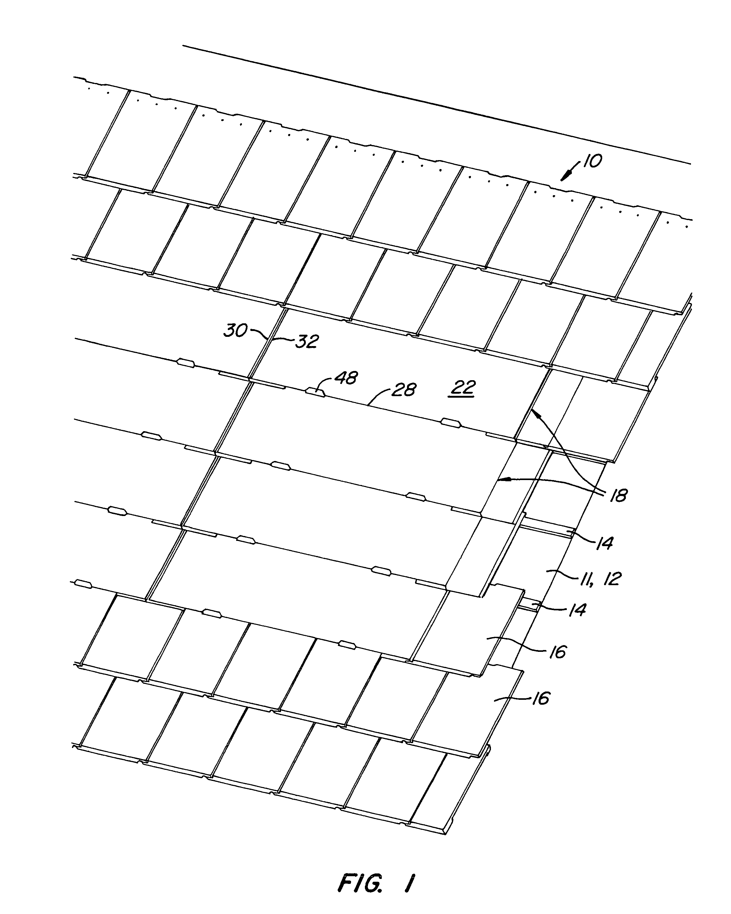
[0020]FIG. 1 illustrates a roofing system 10 including a roofing support surface 11, support surface 11 comprising a waterproof and radiant barrier layer 12. Layer 12 may be a conventional underlayment, such as a metal foil faced tar sheet sold by MFM Building Products Corp. of Coshocton, Ohio as Peel & Seal. A series of laterally extending battens 14 are mounted to support surface 11 over layer 12. Support surface 12 is covered by conventional concrete tiles 16, such as MonierLifetile sold by MonierLifetile LLC of Irvine, Calif., and an array of photovoltaic (PV) shingle assemblies 18. As used in this application, a shingle covers products used to cover a wall or an inclined roof, or other non-horizontal surfaces, in which the lower end of one shingle overlaps the upper end of an adjacent shingle.

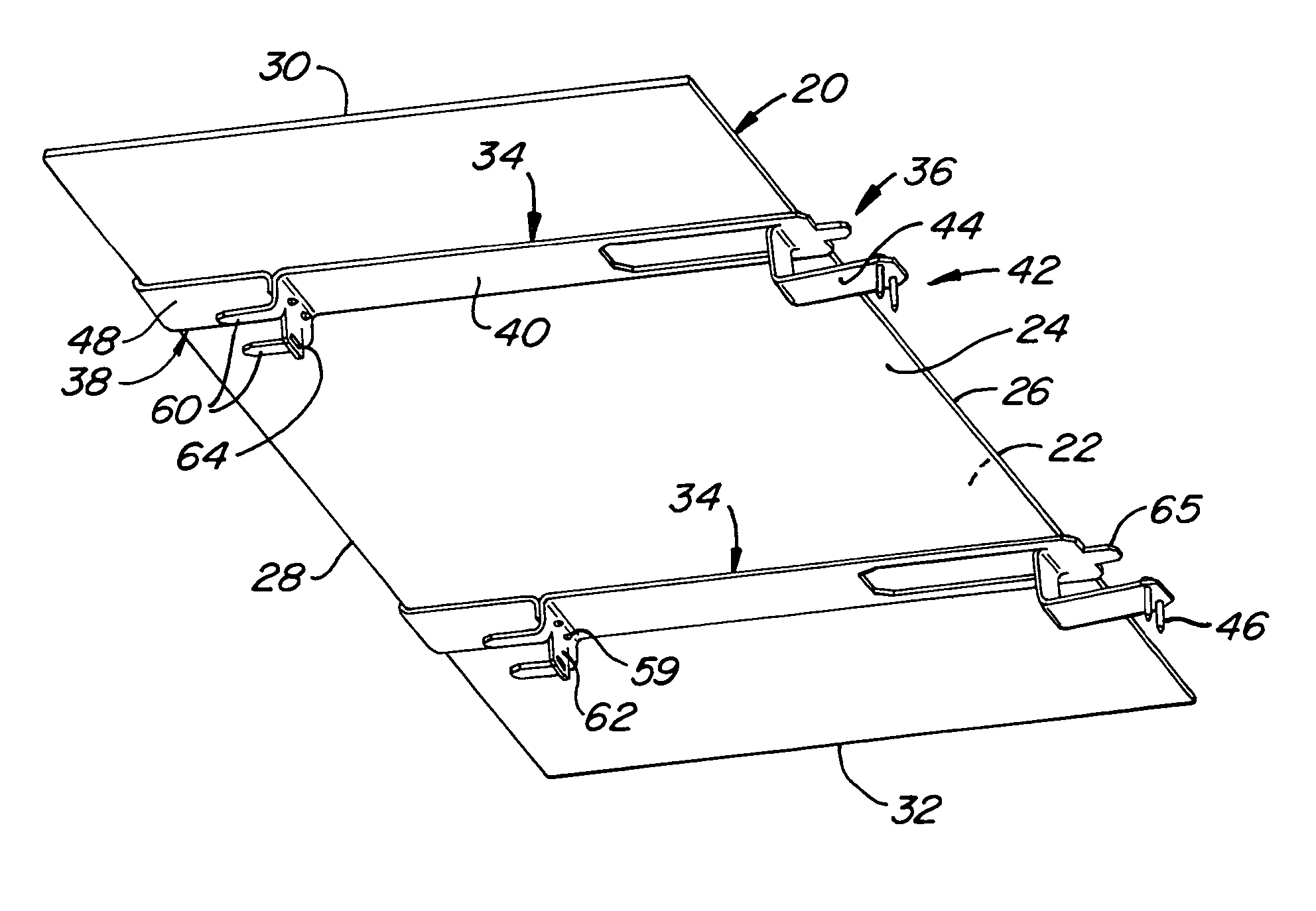
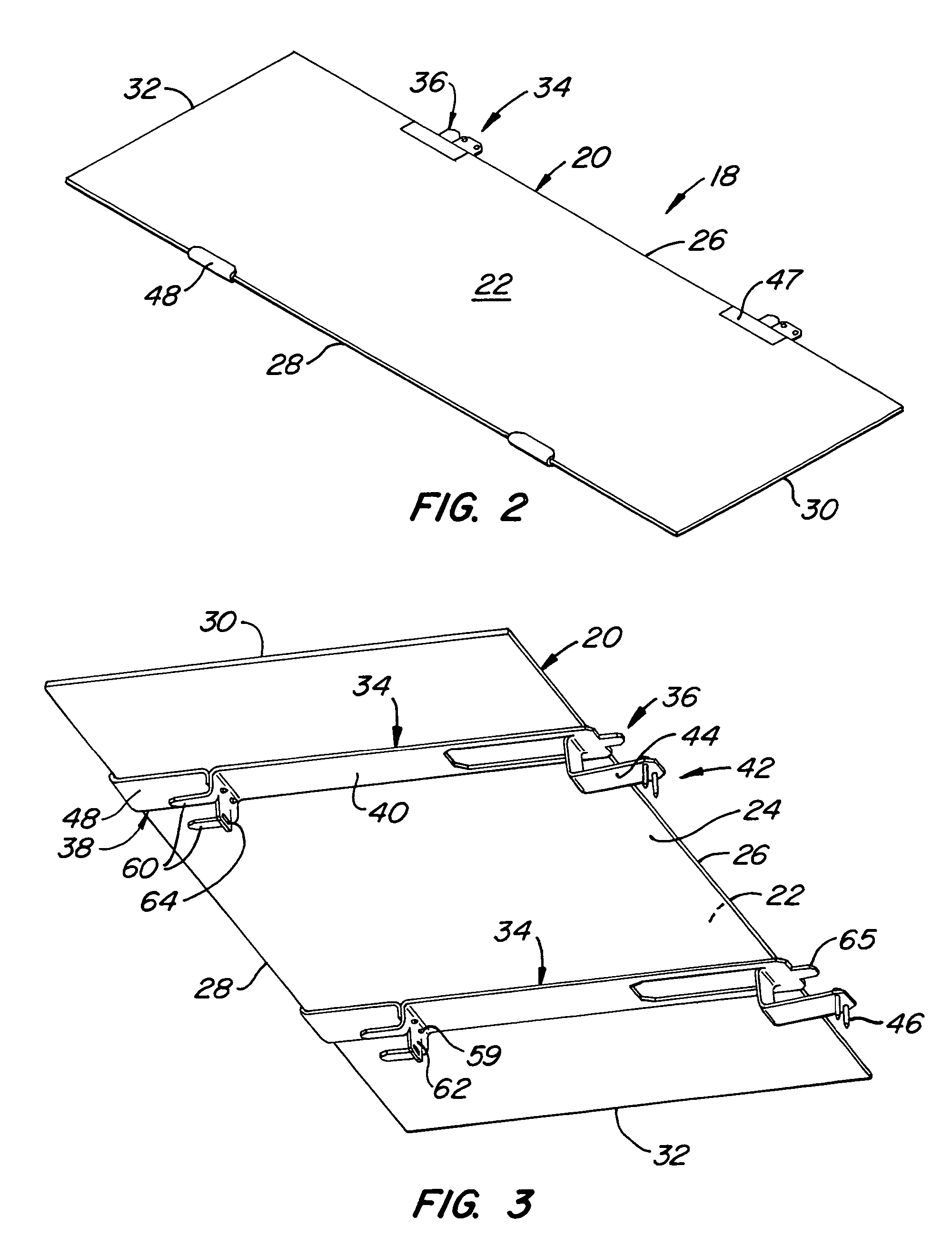
[0021]FIGS. 2 and 3 are enlarged top and bottom isometric views of a shingle assembly shown in FIG. 1. Each shingle assembly 18 comprises a shingle body 20 having upper and lower surfaces ...


PUM


Abstract

A shingle system, mountable to a support surface, includes overlapping shingle assemblies. Each shingle assembly comprises a support bracket, having upper and lower ends, secured to a shingle body. The upper end has an upper support portion, extending away from the shingle body, and an upper support-surface-engaging part, engageable with a support surface so that the upper edge of the shingle body is positionable at a first distance from the support surface to create a first gap therebetween. The lower end has a lower support portion extending away from the lower surface. The support brackets create: (1) a second gap between shingle bodies of the first and second shingle assemblies, and (2) an open region beneath the first shingle assembly fluidly coupling the first and second gaps.

Description

STATE SPONSORED RESEARCH OR DEVELOPMENT[0001]This invention was made with State of California support under California Energy Commission contract number 500-00-034. The Energy Commission has certain rights to this invention.CROSS-REFERENCE TO OTHER APPLICATIONS[0002]None.BACKGROUND OF THE INVENTION[0003]The widespread use of photovoltaic (PV) systems mounted to homes, businesses and factories is generally considered to be a desirable goal. Several factors are believed to be critical to the acceptance of PV systems, in particular by the individual homeowner. Primary among the factors are ease of installation, cost and aesthetics. One way of addressing both cost and aesthetics has been through the use of photovoltaic shingle assemblies. One way such shingle assemblies address the cost issue is by being used as a replacement for conventional shingles, preferably using similar mounting techniques. The aesthetic issue has begun to be addressed by the use of photovoltaic assemblies in the...

Claims


Application Information

Patent Timeline
Patent Type & Authority Patents(United States)
IPC IPC(8): E04D1/34
CPCE04D1/34H02S20/23F24J2/52E04D2001/3414E04D2001/3447E04D2001/3458E04D2001/3473E04D2001/3494F24J2002/0061Y02B10/12Y02B10/20Y02E10/47F24J2/045F24S20/67F24S25/613F24S2020/13Y02E10/50Y02B10/10E04D1/29
Inventor ALMY, CHARLES
Owner SUNPOWER CORPORATION
Why Eureka
Try Eureka