Check reins for artificial disc replacements

a technology of artificial discs and reins, which is applied in the field of check reins for artificial disc replacements, can solve the problems of spinal cord injury, spinal cord injury, and increased probability of spinal cord injury with excessive force in the posterior direction, and achieve the effect of restoring motion limiting functions and preventing excessive spinal motion

Inactive Publication Date: 2007-01-02
FERREE BRET A
View PDF10 Cites 66 Cited by
  • Summary
  • Abstract
  • Description
  • Claims
  • Application Information

AI Technical Summary

Benefits of technology

[0006]This invention is broadly directed to check reins in the form of elongated members used to limit the extreme range of motion which would otherwise be permitted by some ADR designs. The check reins serve two main purposes. First, they retain disc spacers, if present. Additionally, the wedge shape of ADRs and the removal of the Anterior Longitudinal Ligament (ALL) and a portion of the Annulus Fibrosus (AF) to insert the ADR from an anterior approach, favor anterior extrusion of disc spacers. In preferred embodiments the check reins are therefore limited to the anterior portion of the periphery of the ADR. Second, check reins serve to prevent excessive spinal motion. Again, although they may be helpful in other locations, anterior check reins help restore the motion limiting functions of the ALL and AF that were removed in anterior approaches to the spine.

Problems solved by technology

Replacement of cervical discs with synthetic devices that preserve motion could destabilize the cervical spine.
Trauma to a destabilized cervical spine could cause spine cord injury.
Weakening the supporting structures on the anterior portion of the spine increases the probability of spinal cord injury with excessive force from a posterior direction.
Check reins made of inelastic, materials that do not flex well, will limit ADR motion excessively.
Repeated bending of wires risks injury to the surrounding tissues.
First, the bend in stiff wires could impinge the surrounding tissues.
Second, the tissues could be pierced by the ends of broken wires.

Method used


Image

  • Check reins for artificial disc replacements
  • Check reins for artificial disc replacements

Examples


Embodiment Construction

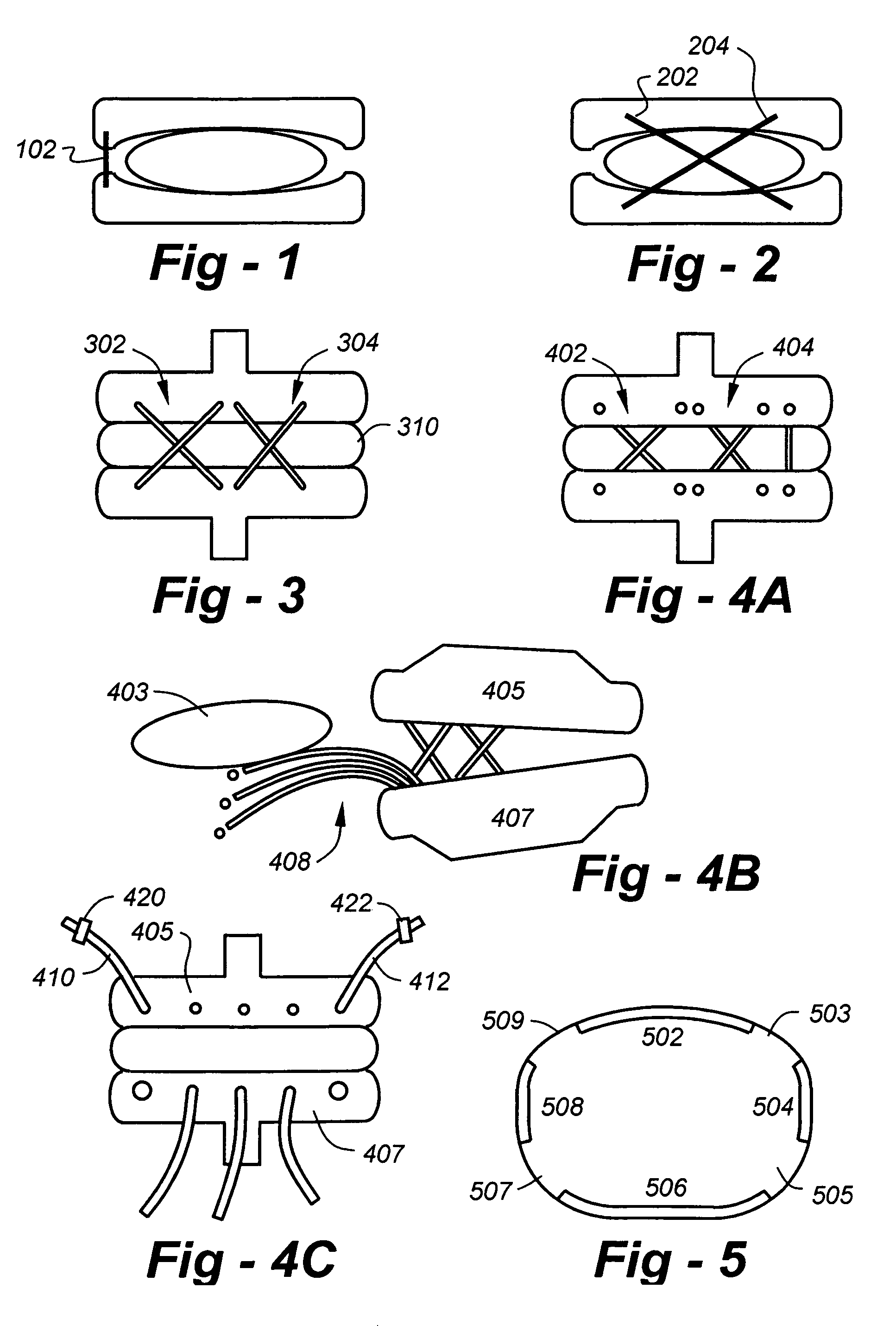
[0014]The invention is broadly directed to check reins in the form of elongated members used to limit the extreme range of motion which would otherwise be permitted by some ADR designs. The check reins serve two main purposes. First, they retain disc spacers, if present. Additionally, the wedge shape of ADRs and the removal of the Anterior Longitudinal Ligament (ALL) and a portion of the Annulus Fibrosus (AF) to insert the ADR from an anterior approach, favor anterior extrusion of disc spacers. In preferred embodiments the check reins are therefore limited to the anterior portion of the periphery of the ADR.

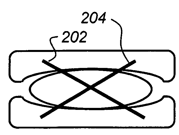
[0015]Second, check reins serve to prevent excessive spinal motion. Again, although they may be helpful in other locations, anterior check reins help restore the motion limiting functions of the ALL and AF that were removed in anterior approaches to the spine. As illustrated in FIG. 2, check reins may helpful in the anterior and posterior portions of ADRs. Check reins may also be...


PUM


Abstract

Check reins in the form of elongated members are used to limit the extreme range of motion which would otherwise be permitted by some ADR designs. The check reins serve two main purposes. First, they retain disc spacers, if present. Additionally, the wedge shape of ADRs and the removal of the Anterior Longitudinal Ligament (ALL) and a portion of the Annulus Fibrosus (AF) to insert the ADR from an anterior approach, favor anterior extrusion of disc spacers. In preferred embodiments the check reins are therefore limited to the anterior portion of the periphery of the ADR. Second, check reins serve to prevent excessive spinal motion. Again, although they may be helpful in other locations, anterior check reins help restore the motion limiting functions of the ALL and AF that were removed in anterior approaches to the spine.

Description

REFERENCE TO RELATED APPLICATION[0001]This application claims priority from U.S. Provisional Patent Application Ser. No. 60 / 375,286, filed Apr. 24, 2002, and is a continuation-in-part of U.S. Patent Application Ser. No. 10 / 421,433, filed Apr. 23, 2003. The entire content of each application is incorporated herein by reference.FIELD OF THE INVENTION[0002]This invention relates generally to artificial disc replacements (ADRs) and, more particularly, to check reins for ADRs.BACKGROUND OF THE INVENTION[0003]Replacement of cervical discs with synthetic devices that preserve motion could destabilize the cervical spine. Trauma to a destabilized cervical spine could cause spine cord injury. Insertion of most types of artificial disc replacements (ADR) requires cutting the anterior longitudinal ligament and removal of a portion of the anterior half of the annulus fibrosis and nucleus pulposus. Weakening the supporting structures on the anterior portion of the spine increases the probability ...

Claims


Application Information

Patent Timeline
Patent Type & Authority Patents(United States)
IPC IPC(8): A61B17/70A61F2/44A61F2/00A61F2/08A61F2/30
CPCA61F2/4425A61F2/08A61F2220/0075A61F2002/30604A61F2002/443A61F2002/30462
Inventor FERREE, BRET A.
Owner FERREE BRET A
Why Eureka
Try Eureka