
Portable vise and saw combination

a technology of sawing saw and portability, which is applied in the direction of metal sawing devices, metal sawing accessories, manufacturing tools, etc., can solve the problems of pipe fitters being unable to assemble pipe sections on the job site, and large pipe sizes are often cut away from the jobsi

Inactive Publication Date: 2007-01-09
AMAESING TOOLS MFG
View PDF56 Cites 34 Cited by
  • Summary
  • Abstract
  • Description
  • Claims
  • Application Information

AI Technical Summary

Benefits of technology

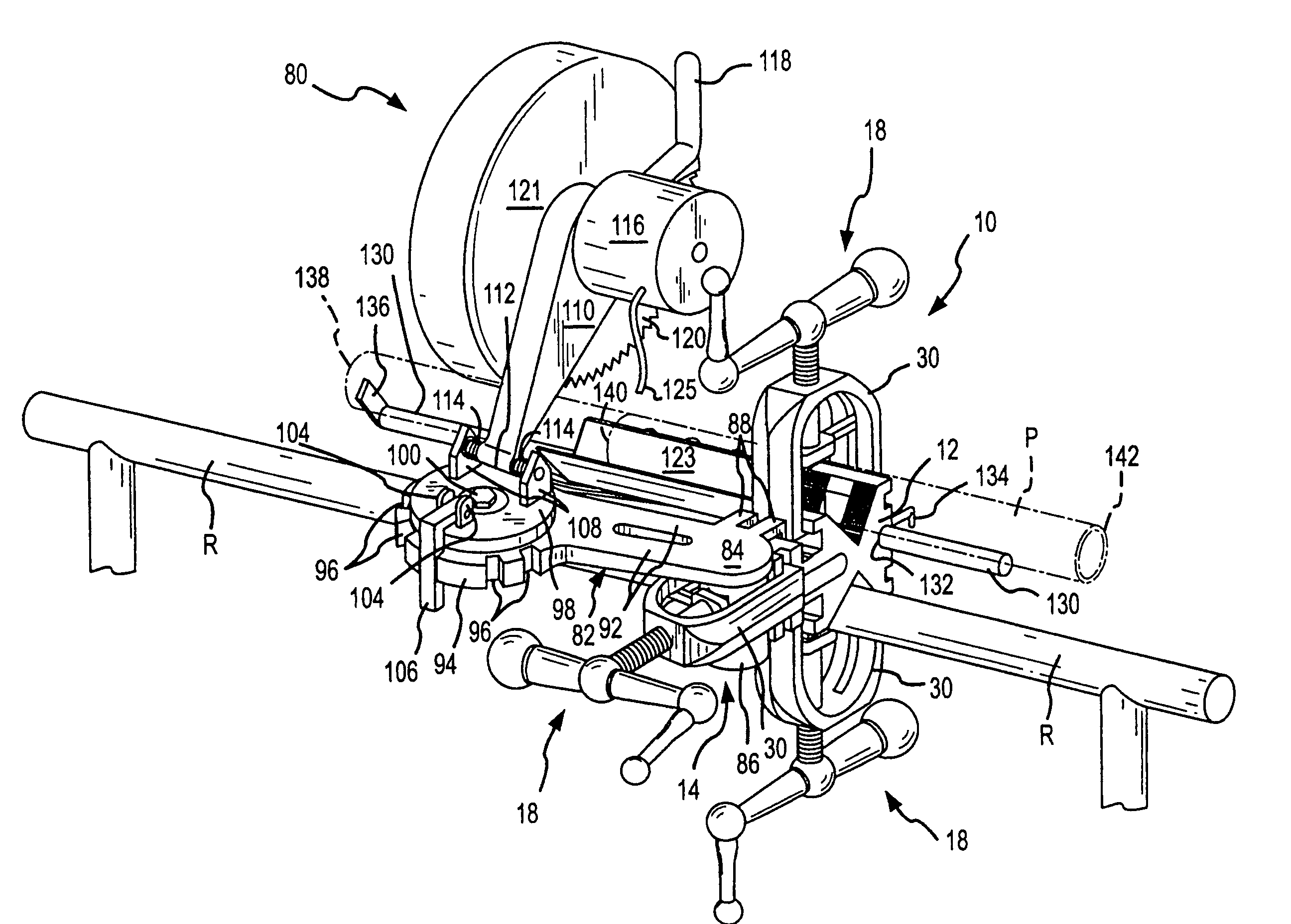
[0011]In accordance with the present invention, a portable vise and saw combination is provided that allows one or more workpieces to be secured in a desired horizontal or vertical orientation, and an integral saw that allows the workpieces to be cut. The portable vise includes three available attachment points. One clamp can be utilized to attach the portable vise to a support, another clamp can be used to secure a workpiece to the vise, and the remaining clamp can be used to secure the saw in an orientation that allows the saw to cut the workpiece. The particular construction of the clamps allows an operator to manipulate the clamps to force a movable jaw against the object to be clamped, yet the operator does not have to manually guide the jaw in order to ensure that it is aligned with the object.

Problems solved by technology

A job site does not typically have a bench or support that is capable of securing the pipes for assembly.
Thus, one continuing problem in pipefitting is the inability for a pipe fitter to assemble sections of pipe at the job site, or to otherwise rework the pipe at the job site.
Preferably, pipe is cut at the jobsite; however, larger pipe sizes are often cut away from the jobsite because the power saw required to cut the pipe may only be incorporated on a large base or table.

Method used


Image

  • Portable vise and saw combination
  • Portable vise and saw combination
  • Portable vise and saw combination

Examples


Embodiment Construction

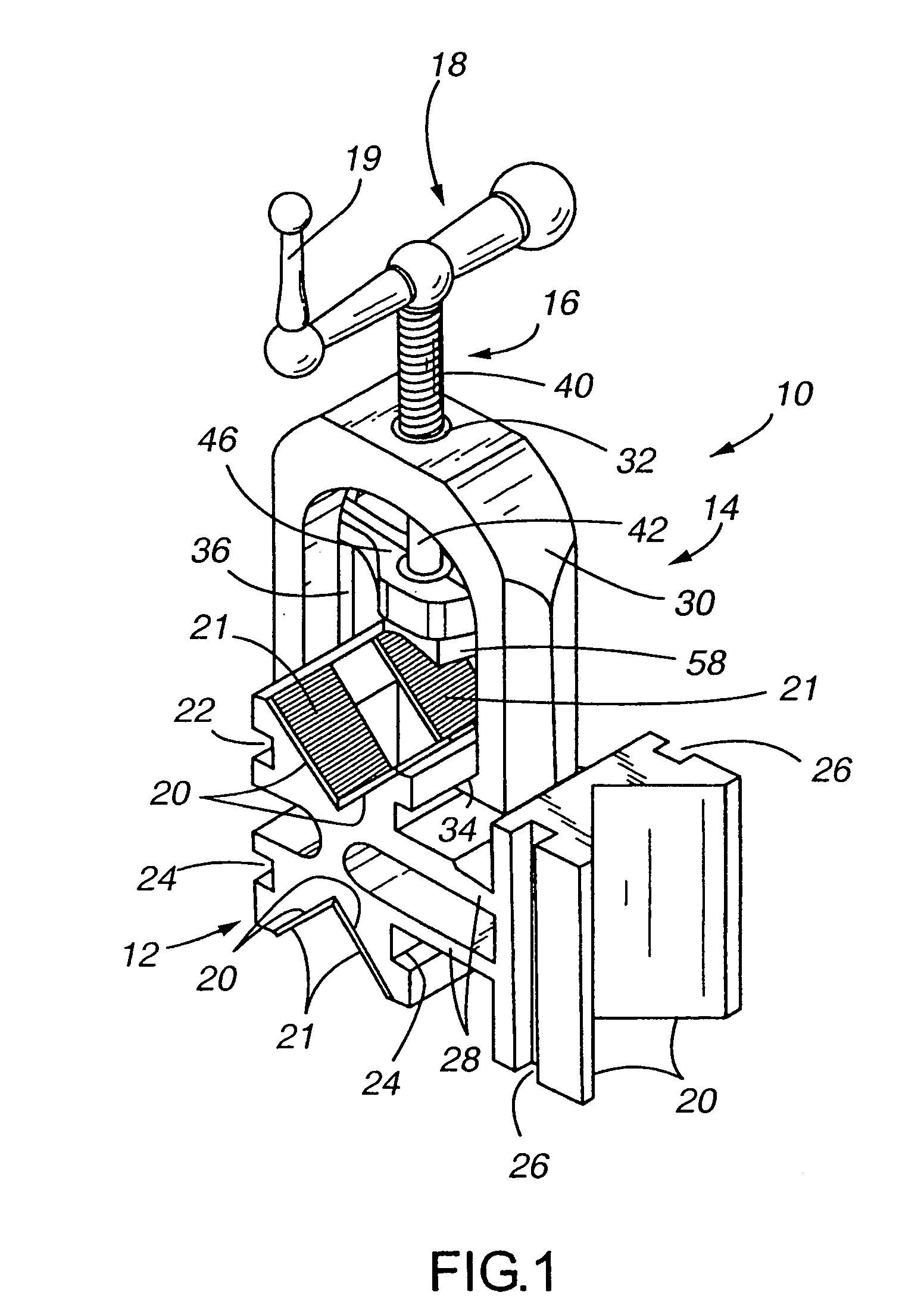
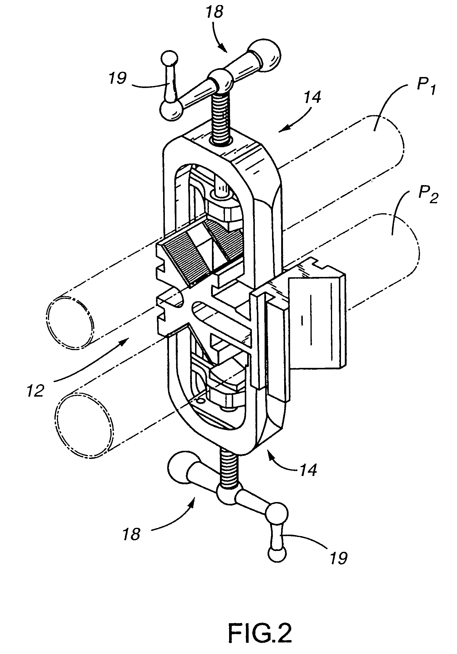
[0027]FIG. 1 illustrates the portable vise that is used in the combination of the present invention. The major components of the vise 10 include a body 12, and one or more clamps 14 that enable the vise to be mounted to a support and to secure one or more workpieces. Beginning first with a description of a clamp 14, it includes a set screw 16 that is threadably received in a threaded collar 32 mounted in a frame 30 of the clamp. A handle 18 attaches to an end of the set screwing allowing an operator to manipulate the set screw 16 which in turn causes travel of the yoke 46. The handle 18 may optionally include a perpendicularly extending knob 19 which further assists an operator in manipulating the set screw.

[0028]The body 12 is defined by three pairs of v-shaped or converging engaging surfaces 20. Two pairs of the engaging surfaces are positioned back to back with one another. The third pair of v-shaped engaging surfaces are arranged orthogonally / perpendicularly with respect to the ...


PUM

PropertyMeasurementUnit
anglesaaaaaaaaaa
angleaaaaaaaaaa
angleaaaaaaaaaa

Abstract

A portable vise and saw combination includes a vise element having three attachment points. One attachment point is used to attach the vise to an existing support such as an existing horizontal rail, and another attachment point allows a saw to be mounted to the vise. A workpiece is mounted in the third attachment point. The saw is aligned with the workpiece so that the workpiece may be selectively cut at a desired length and angle. A measuring apparatus is also incorporated within the vise to allow an operator to set the saw to cut successive workpieces at the same lengths without having to remeasure each workpiece.

Description

CROSS REFERENCE TO RELATED APPLICATION[0001]This application is a CIP of patent application Ser. No. 10 / 773,781, filed on, Feb. 6, 2004 entitled “Portable Vise”, the disclosure of which is incorporated by reference herein.TECHNICAL FIELD[0002]The present invention relates to the field of clamping devices that secure a workpiece, and more particularly, to a portable vise especially adapted for pipefitting to secure one or more workpieces that extend horizontally or vertically, and the vise further including an integral saw enabling the workpieces to be cut.BACKGROUND OF THE INVENTION[0003]There are numerous known clamping devices that allow an operator to hold and securely restrain a workpiece. One well-known clamping design is a vise clamp having one stationary jaw, and one movable jaw that may be adjusted to clamp the workpiece between the jaws.[0004]Welders and pipe fitters often use a clamp to secure a workpiece such as a length of pipe that must be cut, or welded to another leng...

Claims


Application Information

Patent Timeline
Patent Type & Authority Patents(United States)
IPC IPC(8): B26D7/02B25B1/20B23D45/12B23D47/00B23D47/06B23D59/00B26D7/06
CPCB23D45/12B23D59/007B23D47/06B23D47/00Y10T83/7487Y10T83/0596Y10T83/7693Y10T83/7788Y10T83/75Y10T83/667
Inventor MAES, ROGER V.
Owner AMAESING TOOLS MFG
Learn More