
Mop assembly and cart

a technology of mop and assembly, which is applied in the direction of cleaning machines, carpet cleaners, hand devices, etc., can solve the problems of difficult clean up situations, affecting the operation of the liquid delivery system on the mop, and the valve to become sticky or even plugged, so as to achieve quick and easy change

Inactive Publication Date: 2007-01-09
3M INNOVATIVE PROPERTIES CO
View PDF21 Cites 44 Cited by
  • Summary
  • Abstract
  • Description
  • Claims
  • Application Information

AI Technical Summary

Benefits of technology

[0005]The present invention provides a mop assembly for applying liquids (e.g., floor coatings, floor cleaners, floor sealers, floor finishes, disinfectants, etc.) that is generally of the type described above, but in which the structure of the valve assembly restricts the valve assembly from becoming sticky when it is not cleaned between uses, and, should the valve assembly become disabled by thickened or solidified liquids, allows the only part of the valve assembly in which such thickened or solidified material can occur to be quickly and easily changed by a person using the mop assembly.
[0008]Thus, any thickening or solidification of liquid being dispensed due to improper cleaning of the valve assembly will occur in the length of tubing, and in the event that movement of liquid through the length of tubing becomes restricted or stopped because of such thickened or solidified material in the length of tubing, the length of tubing can either be stretched and squeezed to help pass the thickened or solidified material, or can easily and quickly be replaced by a person using the mop assembly.
[0009]In an embodiment of the mop assembly described herein the handle has a central passageway, the second member of the valve assembly is fixed with respect to the handle and forms an end to the passageway, and the first member of the valve assembly comprises a first part within and moveable longitudinally along that passageway. The portion of the length of tubing between its inlet and outlet ends extends transverse of the handle and the passageway between the first and second members of the valve assembly, and the valve assembly includes a spring biasing those members to their closed position. A manually engageable trigger member is pivotally mounted on the handle at its end opposite the mop head, and is connected by a connecting member within the passageway to the first member of the valve assembly so that manual pivoting of the trigger can move the first member to the open position of the valve members and thereby allow liquid to be dispensed on the surface.

Problems solved by technology

While such mop assemblies can be used effectively if they are thoroughly cleaned between each use, a significant problem can occur if certain liquids such as floor waxes or the like are allowed to remain in the valve assembly between uses.
Such liquids can thicken and / or solidify when exposed to the atmosphere through the outlet opening of the valve, causing the valve to become sticky or even plugged because of the thickened or solidified material, and presenting a difficult clean up situation before the liquid delivery system on the mop will again operate properly.

Method used


Image

  • Mop assembly and cart
  • Mop assembly and cart
  • Mop assembly and cart

Examples


Embodiment Construction

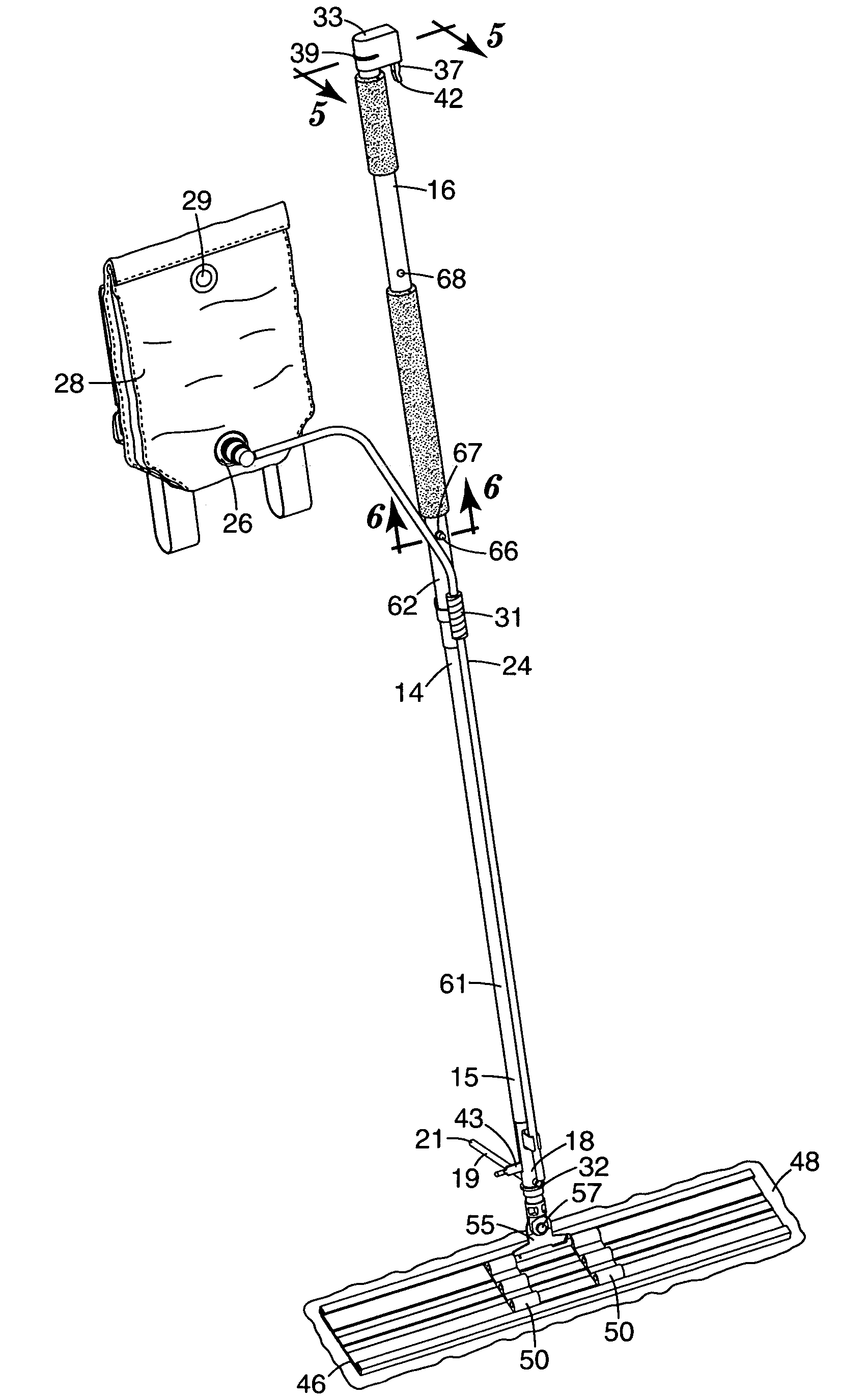
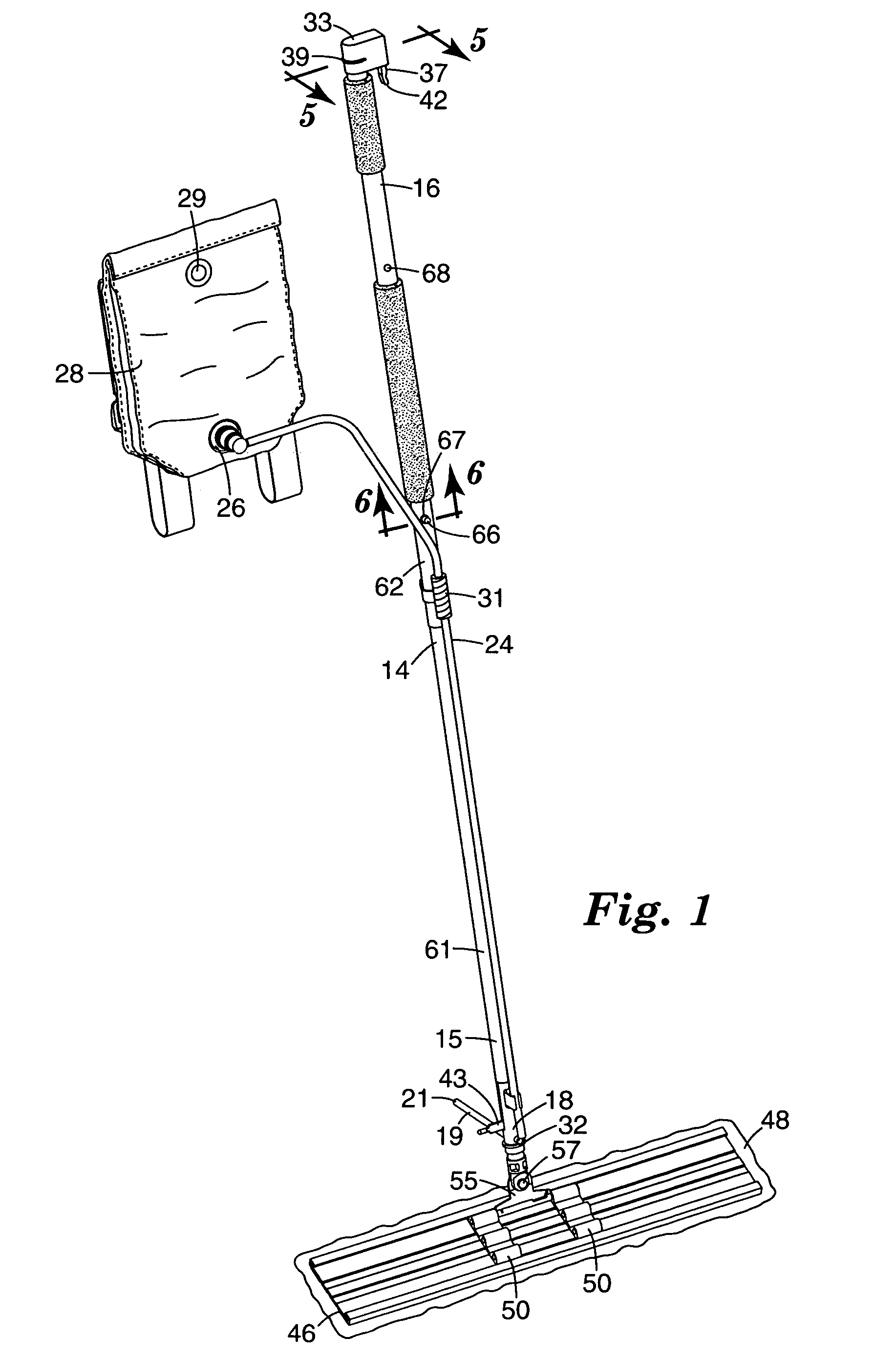
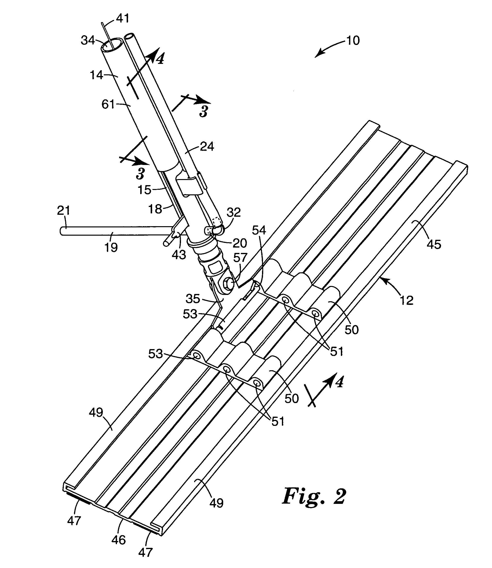
[0023]Referring now to FIGS. 1 through 4 of the drawing there is illustrated a mop assembly 10 according to the present invention that can be used for applying liquid (e.g., floor coatings, floor cleaners, floor sealers, floor finishes, disinfectants, etc.) to a surface such as the surface of a floor.

[0024]The mop assembly 10 comprises a mop head 12, an elongate handle 14 having a first end 15 pivotally attached to the mop head 12, and a portion adjacent an opposite second end 16 that is adapted to be manually engaged to move the mop head 12 along the surface. A valve assembly 18 mounted on the handle 14 adjacent its first end 15 has inlet and outlet openings at and provided by opposite ends 20 and 21 of a length 19 of resiliently flexible elastic tubing (e.g., 5 / 16 O.D. latex tubing) included in the valve assembly 18 that has a portion extending transversely through the handle 14. The valve assembly also includes first and second members 22 and 23 in the handle 14 on opposite sides...


PUM


Abstract

A mop assembly including a mop head and handle, and a supply of liquid connected to a valve assembly on the handle. The valve assembly includes a replaceable length of resiliently flexible tubing having a portion extending transversely through the handle and members on opposite sides of the length of tubing that are relatively movable between a closed position pinching together opposite sides of the tubing to stop the flow of liquid through it, and a spaced open position affording flow of liquid through the tube. A storage cart includes a main portion and a tray portion having a receptacle for receiving the mop head mounted on the main portion for relative movement between a vertical closed position at which the main portion covers an open side of the receptacle; and a horizontal open position at which the mop head can be inserted into or removed from the receptacle.

Description

CROSS REFERENCE TO RELATED APPLICATION[0001]This application is a continuation of U.S. application Ser. No. 10 / 454,051, filed Jun. 4, 2003, issued as U.S. Pat. No. 6,854,912, the disclosure of which is herein incorporated by reference.FIELD OF THE INVENTION[0002]The present invention relates to mop assemblies of the type used for applying liquids (e.g., floor coatings, floor cleaners, floor sealers, floor finishes, disinfectants, etc.) to a surface such as the surface of a floor, which mop assemblies include a mop head, a handle pivotally attached to the mop head by which the mop head can be manually moved along the surface; a valve assembly mounted on the handle adjacent the mop head connected by a hose to a supply of liquid supported above the mop head, which valve is normally closed to stop the flow of liquid through the valve but can be manually opened to allow liquid from the container to flow through the valve and be deposited on the surface at a position close to the mop head...

Claims


Application Information

Patent Timeline
Patent Type & Authority Patents(United States)
IPC IPC(8): A47L13/26A47L13/22A47L13/30A47L13/51B62B1/26
CPCA47L13/22A47L13/30B62B1/26A47L13/51B62B2202/50
Inventor DYER, JOHN J.OLSON, GARY L.MAURER, DAVID A.MAURER, RAYMOND NFODROCY, JOSEPH J.
Owner 3M INNOVATIVE PROPERTIES CO
Learn More