Carton erecting apparatus

a carton and erecting technology, applied in the field of carton erecting apparatus, can solve the problems of substantially greater and achieve the effect of reducing the length and width of flat folded carton blanks

Inactive Publication Date: 2007-01-16
THIELE TECH
View PDF18 Cites 11 Cited by
  • Summary
  • Abstract
  • Description
  • Claims
  • Application Information

AI Technical Summary

Benefits of technology

[0006]One of the objects of this invention is to provide new and novel vacuum assemblies for removing a flat folded carton from a hopper in a manner facilitating the opening of the carton to an erect condition. Another object of this invention is to provide new and novel flight devices and the mounting thereof for receiving a carton from rotary transfer mechanism and more positively retaining the carton in an opened squared position as the open carton is longitudinally forwardly moved away from the position the vacuum assembly releases its gripping engagement therewith.

Problems solved by technology

Problems have been encountered in erecting flat folded carton blanks, especially ones that are of substantially greater lengths than their height and width when in their erected condition.

Method used


Image

  • Carton erecting apparatus
  • Carton erecting apparatus
  • Carton erecting apparatus

Examples


Embodiment Construction

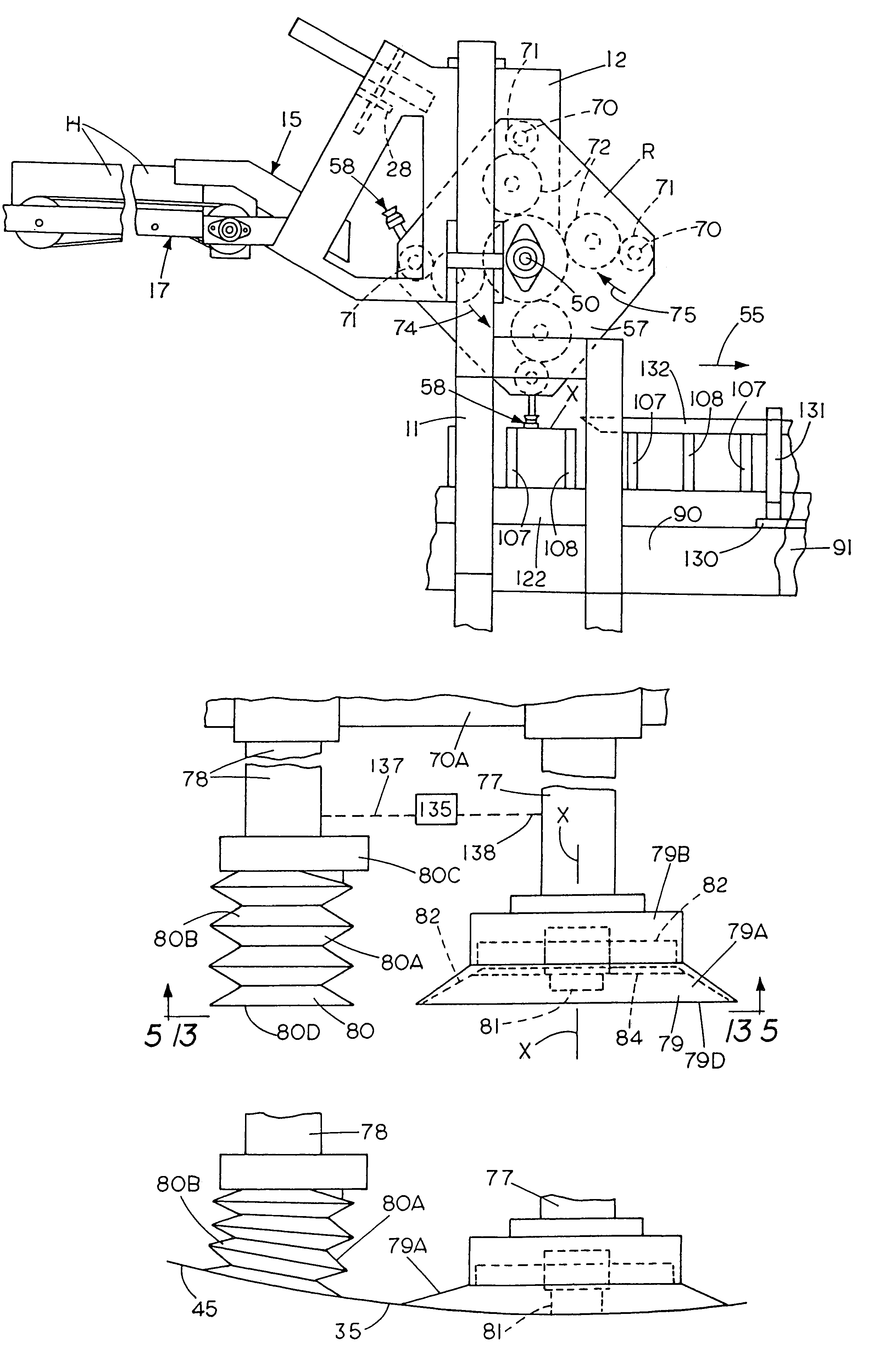
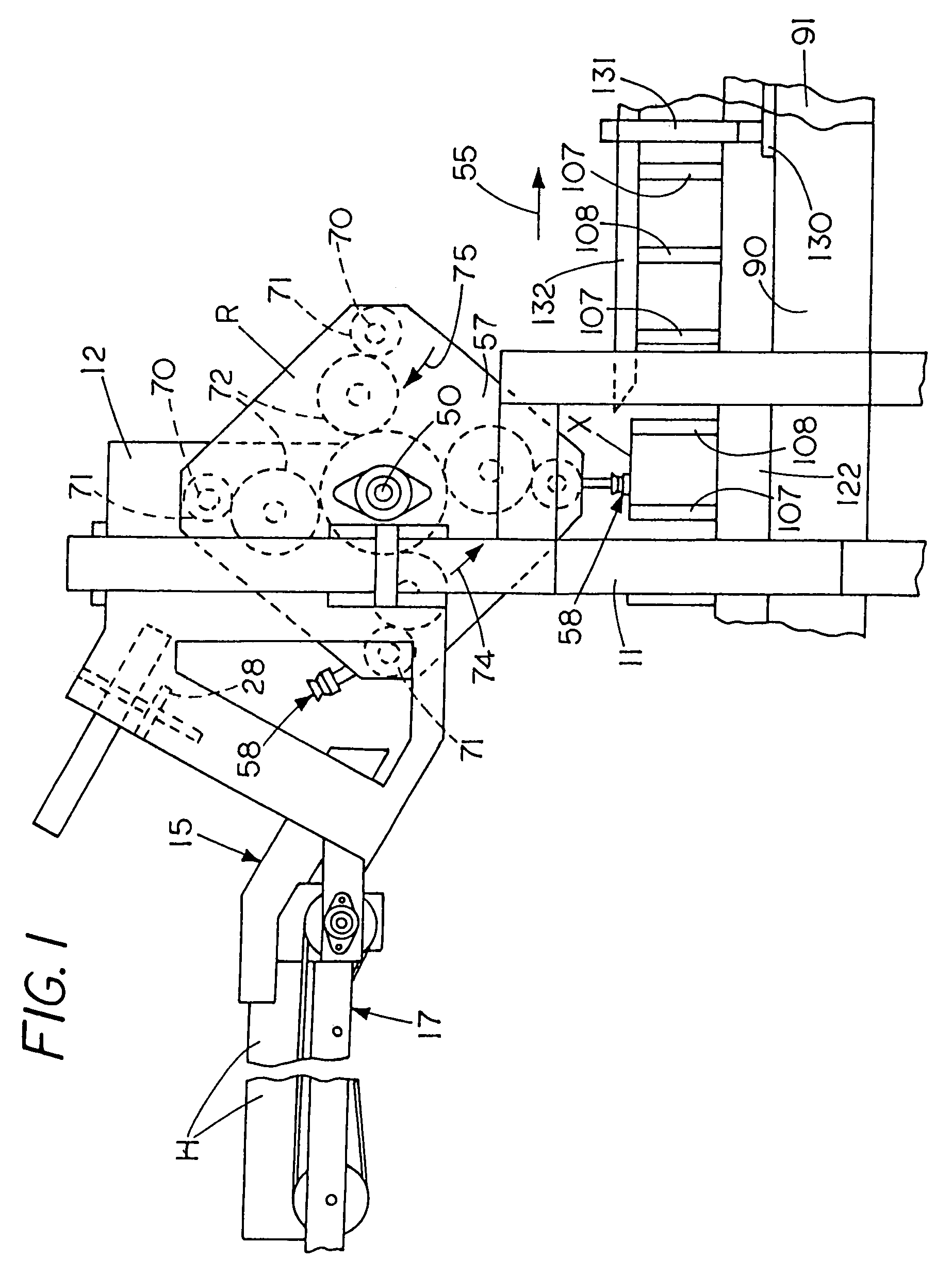
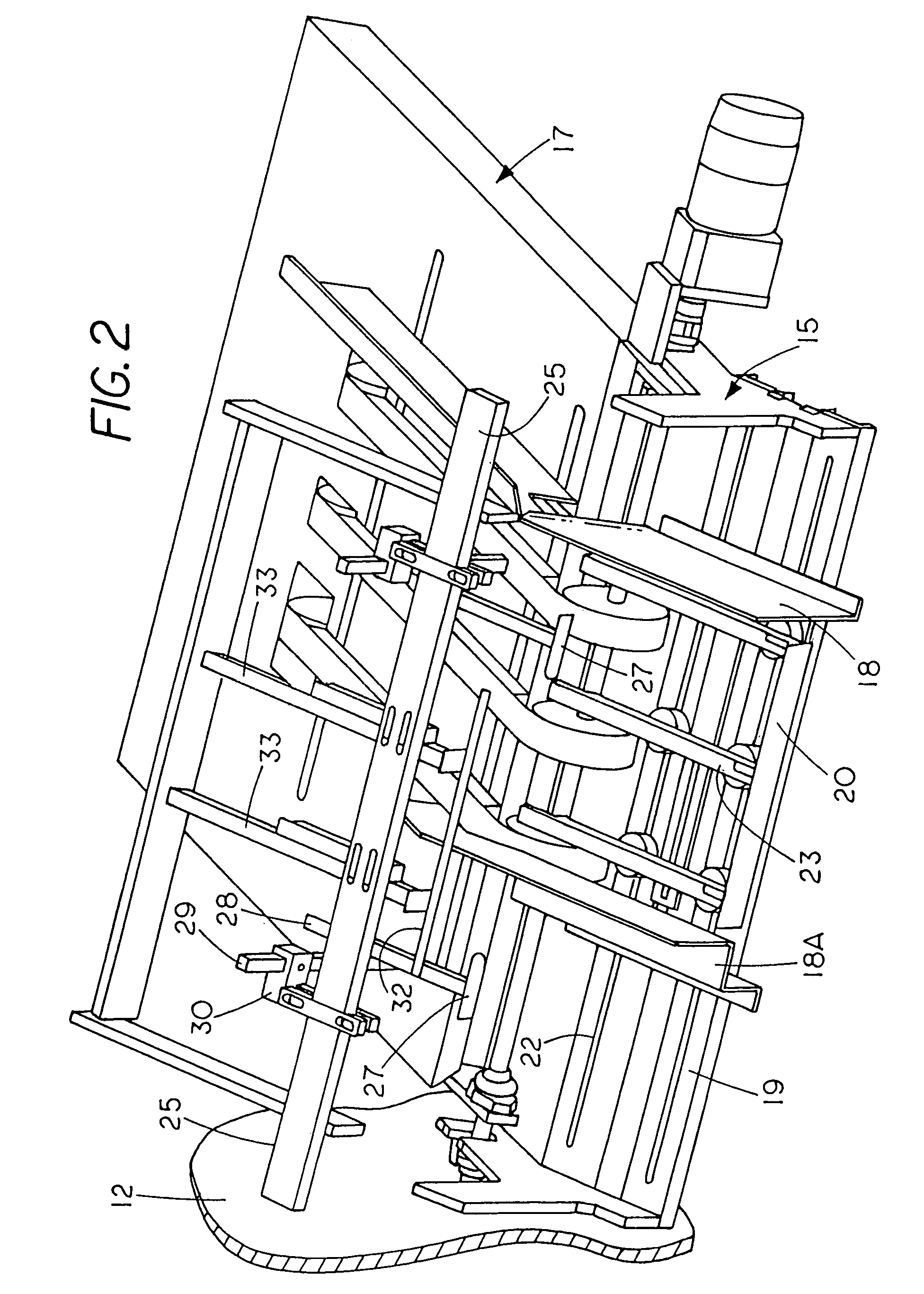
[0021]Referring to the drawings, the case erecting apparatus of this invention includes a frame F having longitudinally elongated frame members 11 and mounting plates 12 that are mounted to the frame members 11. The mounting plates 12 mount a storage hopper H. The hopper includes a front chute, generally designated 15 mounted to the mounting plates and is inclined downwardly and forwardly, and endless hopper conveyer mechanism, generally designated 17 extending rearwardly of the chute. The chute includes side walls 18, 18A transversely adjustably secured to a chute plate 19 by suitable mechanism, for example, clamp bolts (not shown) extended through the slots 22 in the chute plate, and forwardly and downwardly inclined slide bars 23 that are mounted to the chute plate to receive flat folded cartons X from the conveyor 17. The front ends of the slide bars mount a transverse bottom retainer 20 to limit the forward movement of the forwardmost folded carton on the chute. The bottom reta...


PUM


Abstract

Rotary transfer mechanism is mounted on a frame for removing a flat folded carton from a storage hopper to move the carton to a flight conveyor assembly and in cooperation therewith erect the carton to be in an open rectangular condition. The transfer mechanism includes end plates rotated in one angular direction and vacuum cup assemblies rotated therewith and relative thereto in the opposite angular direction. The cup assemblies include transversely opposite cups having adjacent sides less flexible than their remote sides and intermediate cups having buttons therein to form dimples in a carton panel when grippingly engaged. The flight assembly includes guideways to have lugs of flight devices extend into their channels as devices move along the upper run of an endless conveyor. The flight devices include flight bars extending vertically above the lugs as the lugs move in said channels.

Description

BACKGROUND OF THE INVENTION[0001]This invention relates to apparatus for removing flat folded cartons from a hopper and erecting (opening) them.[0002]U.S. Pat. No. 3,302,946 to Anderson disclose a rotary coupon placer that includes a spider mounted for rotation and angularly spaced shafts mounted by the spider for rotation relative thereto and rotation therewith. Each of the shafts mounts a vacuum cup. As the spider rotates the shafts are rotated relative to the spider whereby coupons are removed from a hopper to be applied to a package. As shown in the drawings, the spider is rotated in a clockwise direction and the shafts are rotated in a counterclockwise direction.[0003]U.S. Pat. No. 4,530,686 to Everson et al discloses rotary transfer mechanism, a rotary plate, a fixed gear and planetary gears wherein as the plate is rotated, through the planetary gears, shafts 22 are rotated relative to the plate in opposite angular directions relative to the direction of rotation of the plate....

Claims


Application Information

Patent Timeline
Patent Type & Authority Patents(United States)
IPC IPC(8): B31B1/04B31B1/32B31B50/04B31B50/32
CPCB31B1/06B31B1/80B31B2201/027B31B2203/084B31B2201/289B31B2203/003B31B2201/287B31B50/00B31B50/80B31B2100/00B31B2120/30B31B50/062B31B50/804B31B2100/0024
Inventor FULKERSON, GREGORY M.ERICKSON, RICHARD A.
Owner THIELE TECH
Why Eureka
Try Eureka