
Eureka
For R&D, Eureka makes reading and utilizing patents & technical documents easy.
Eureka AIR
Designed for self-driven R&D workflows. Generate viable solutions, solve complex R&D challenges, empower your innovation with AI.

Eureka Materials
Designed for material experts only. Revolutionize your material R&D, from search, analyze, to developing new materials.

TechResearch
Generate reliable direction feasibility study reports for your R&D in just a few steps.

TechSeek
Discover and master advanced knowledge NOW. Basics, ideas, possibilities, all at once.

TechMind
As an expert in R&D Theories, TechMind can generates customized viable solutions instantly.

TechRisk
Analyze your overall solution with one click, know your potential R&D risks in advance.

TechMonitor
Get weekly tech updates, stay abreast of the latest tech innovations and key insights.
Flanged interbody spinal fusion implants
- Summary
- Abstract
- Description
- Claims
- Application Information
AI Technical Summary
Benefits of technology
Problems solved by technology
Method used
Image

Examples
Example
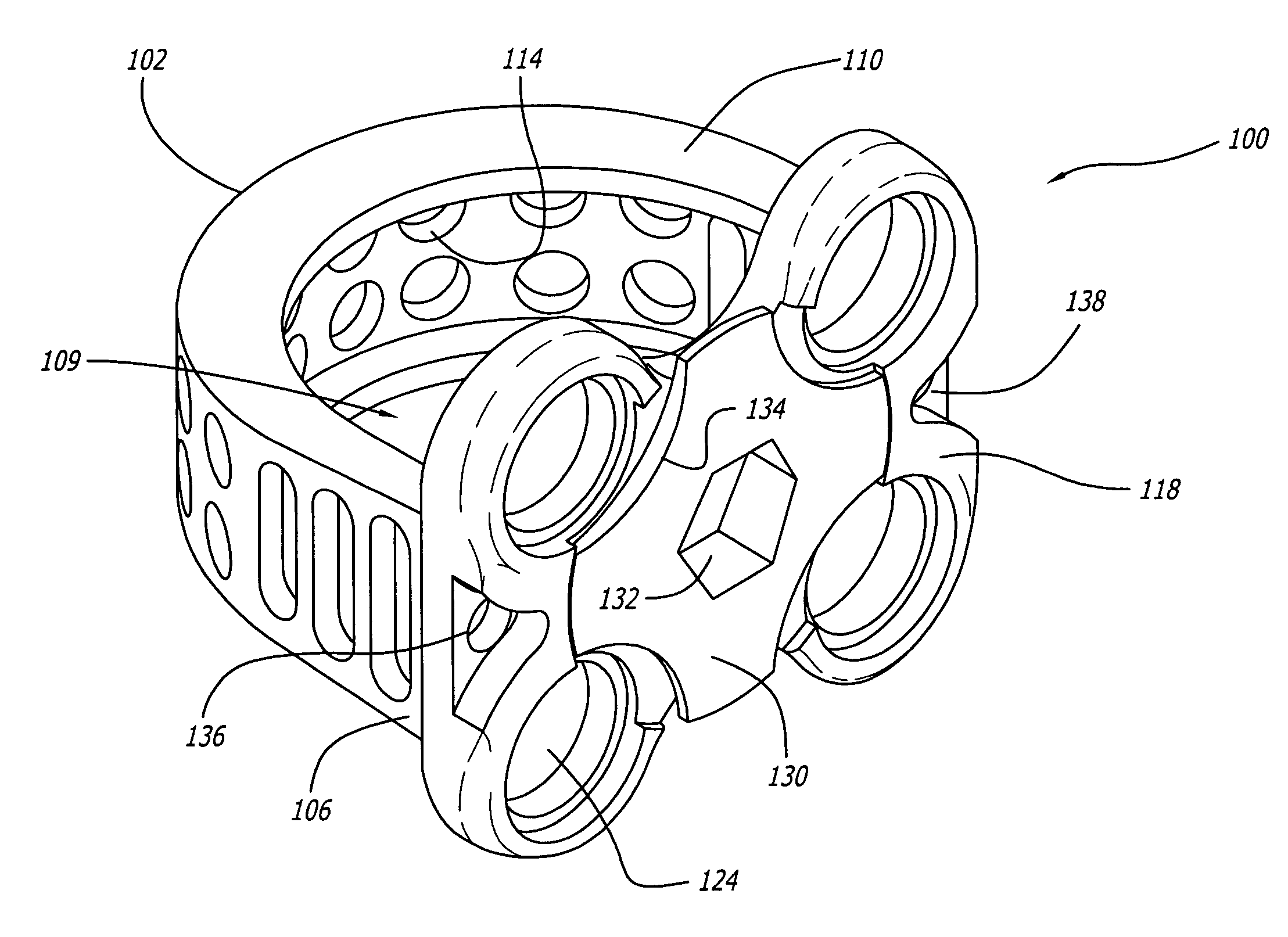
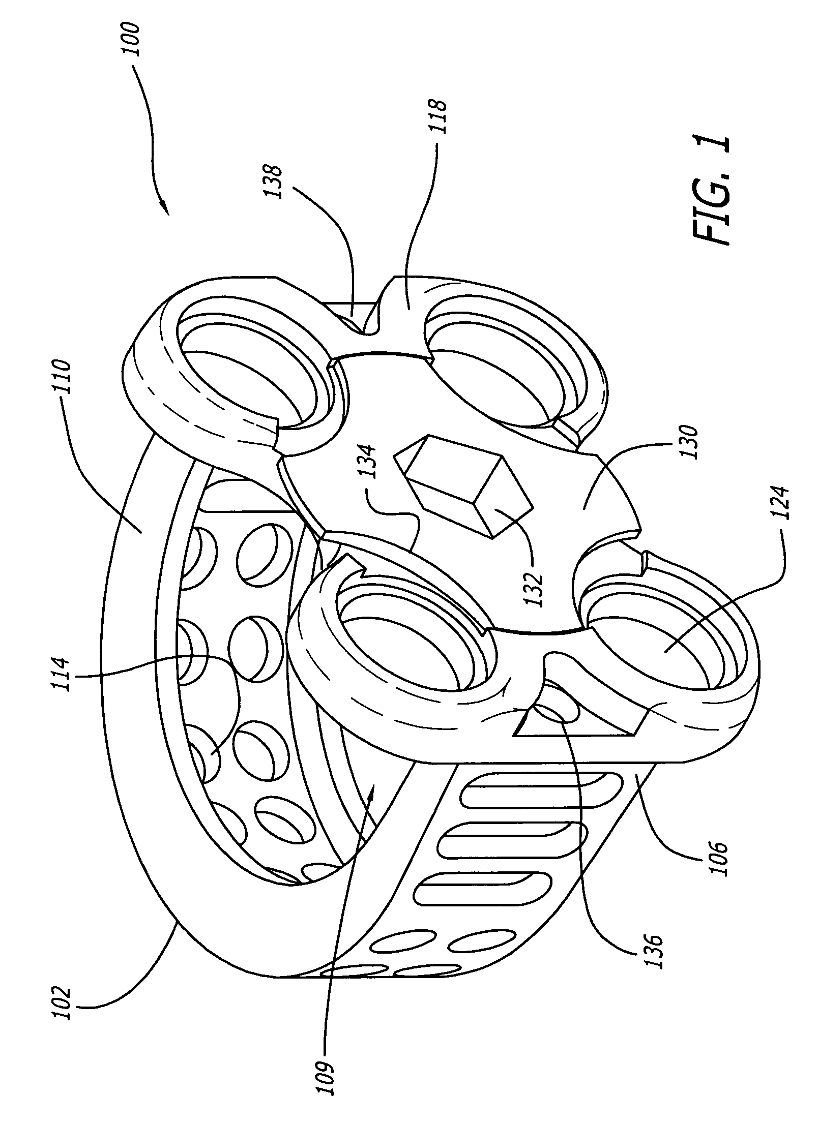
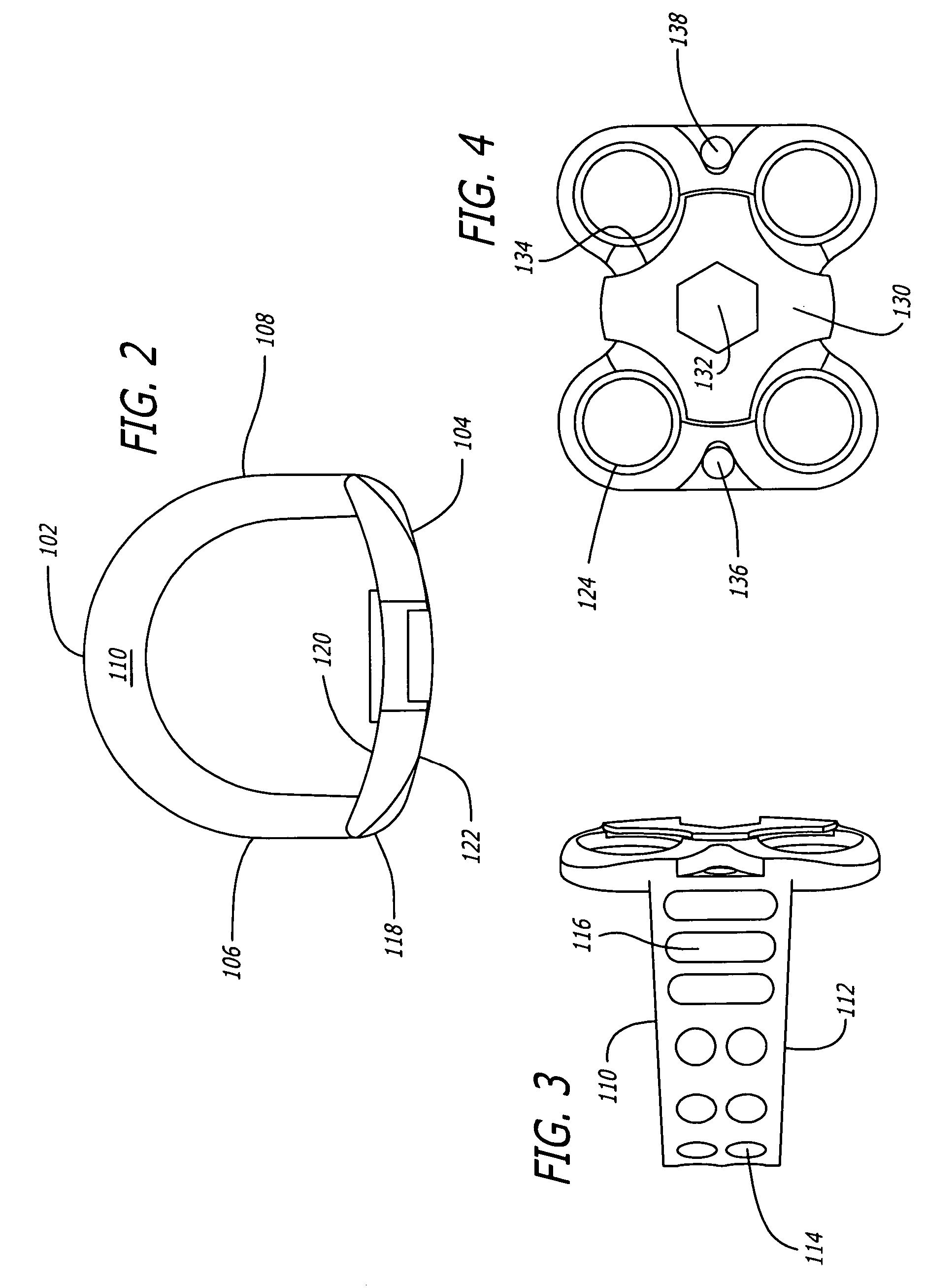
[0041]As shown in FIGS. 1–4, a first embodiment of the spinal implant of the present invention is generally referred to by the numeral 100. As used herein, the term “implant” includes any interbody spinal fusion implant regardless of the material from which it is formed, including specifically surgical quality metal, plastics, ceramics, cortical bone, and other material useful for the intended purpose, including materials that may be in whole or in part bioresorbable. Implant 100 has a leading end 102, an opposite trailing end 104, and sides 106 and 108 therebetween for connecting, spanning, or joining, ends 106, 108.
[0042]In a preferred embodiment, leading end 102 can be a portion of a circle and where the depth of the implant is sufficient, leading end 102 is a portion of a circle. The implant width can be equal to that portion of the circle, or if a half circle, then the diameter of that circle. Alternatively, leading end 102 may be straight at least in part, and for example the ...
Example
[0052]As shown in FIGS. 5–11, a second embodiment of a spinal implant in accordance with the present invention is shown and generally referred to by the reference numeral 200. Implant 200 is similar to implant 100, except that flanged portion 218 includes two locking mechanisms 230, each locking two bone screws to spinal implant 200. Locking mechanisms 230 are preferably positioned each in a recess formed in flanged portion 218 and are configured to permit the insertion of bone screws into bone screw receiving holes 224 while locking mechanisms 230 are in the unlocked position. In a preferred embodiment, locking mechanisms 230 can turn 180 degrees to be fully tightened. Locking mechanisms 230 can both turn clockwise or one counter to the other.
[0053]As shown in FIG. 9, implant 200 is inserted into an implantation space formed across the disc space into the adjacent vertebral bodies. As an example, the implantation space can be prepared with the methods and instrumentations disclosed...
Example
[0072]As shown in FIG. 25, a third embodiment of the spinal implant of the present invention is shown and generally referred to by the reference numeral 300. Implant 300 may be similar to implant 200, except that flanged portion 318 does not include a multi-locking mechanism. Instead, implant 300 has single lock locking mechanisms 330a–d that coaxially engage bone screw receiving holes 324 to individually lock each of bone screws 370 to spinal implant 300. Flanged portion 310 further includes bone through-growth or vascular access holes 396 to allow for the growth of bone and vascularity through implant 300. A dual stage locking tool 392 (such as a screw driver) is used to install bone screws 370 and to install locking mechanism 330 to lock bone screw 370 to the flanged portion 318 with locking mechanism 330. This two stage driver is capable of carrying both the bone screw and the screw lock simultaneously. Driver instrumentation to lock the bone screws to implant 300 may, but need ...
PUM
| Property | Measurement | Unit |
|---|---|---|
| Length | aaaaa | aaaaa |
| Width | aaaaa | aaaaa |
| Height | aaaaa | aaaaa |
Abstract
Description
Claims
Application Information
 - R&D Engineer
- R&D Manager
- IP Professional
- Industry Leading Data Capabilities
- Powerful AI technology
- Patent DNA Extraction
Browse by: Latest US Patents, China's latest patents, Technical Efficacy Thesaurus, Application Domain, Technology Topic, Popular Technical Reports.
© 2024 PatSnap. All rights reserved.Legal|Privacy policy|Modern Slavery Act Transparency Statement|Sitemap|About US| Contact US: help@patsnap.com