Eureka AIR delivers breakthrough ideas for toughest innovation challenges, trusted by R&D personnel around the world.

Filtration device

Inactive Publication Date: 2007-01-16
KIMBERLY-CLARK WORLDWIDE INC
View PDF34 Cites 49 Cited by
  • Summary
  • Abstract
  • Description
  • Claims
  • Application Information

AI Technical Summary

Benefits of technology

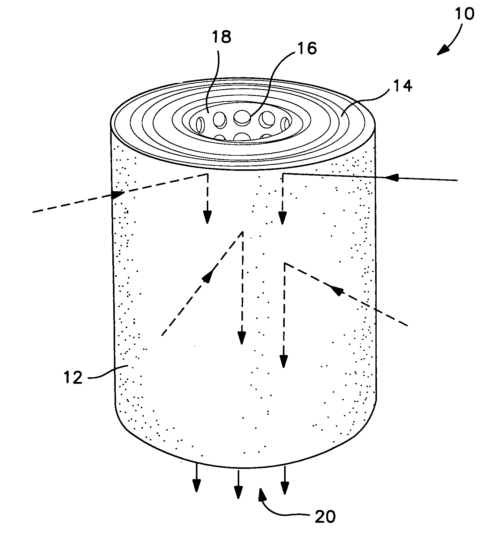
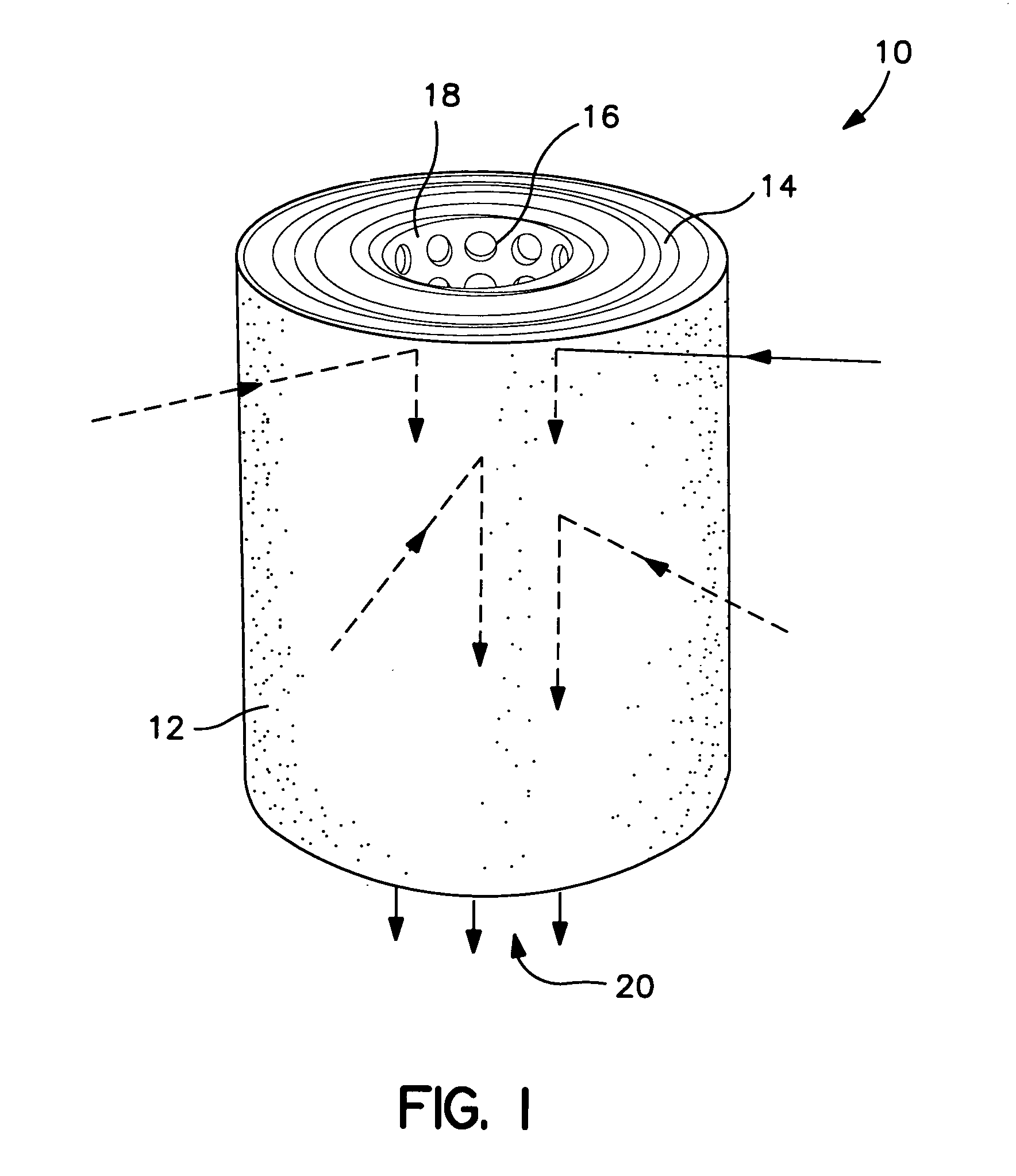
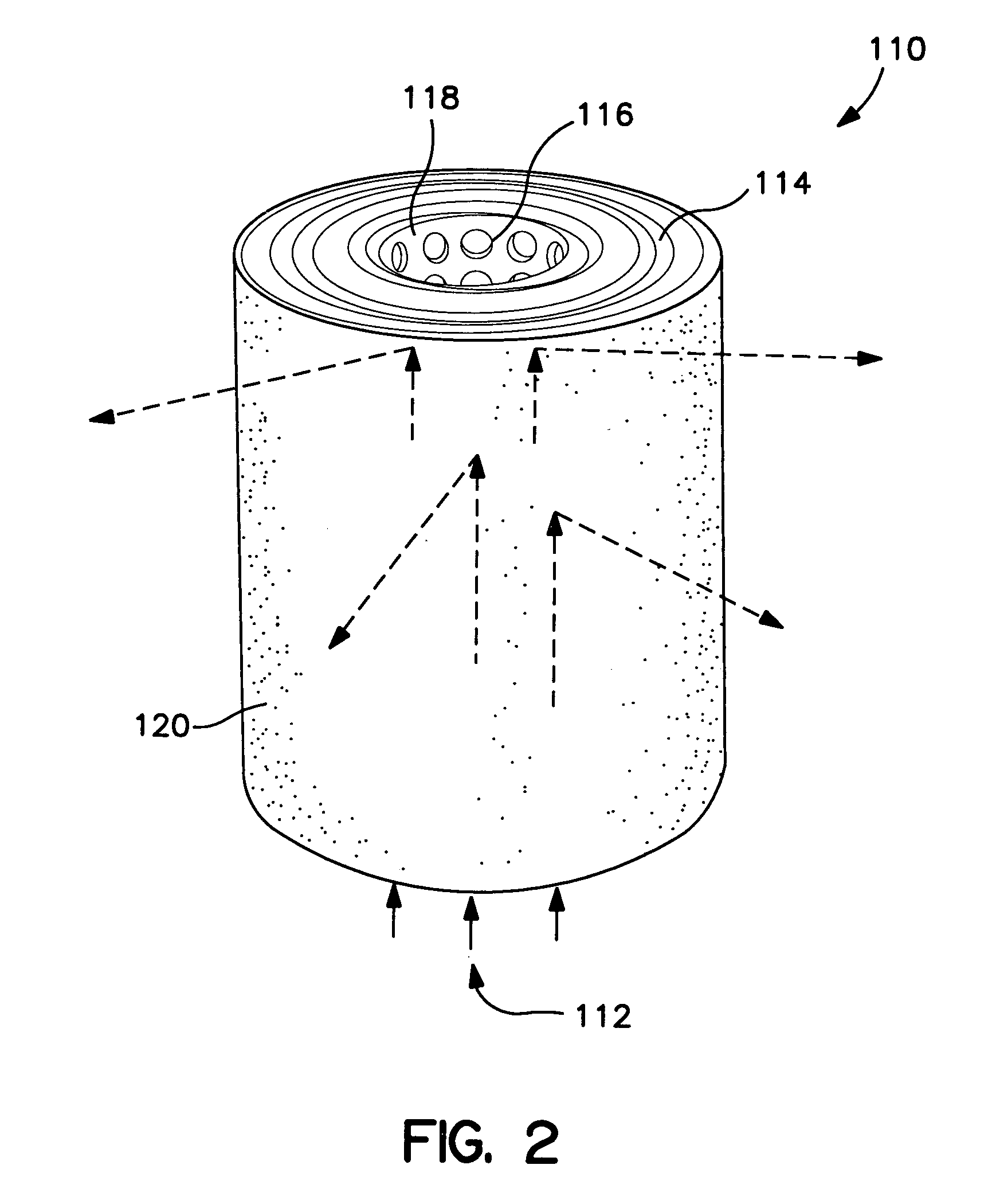
[0017]The present invention exists in various embodiments that may be practiced by those skilled in the art using the teachings found herein. By way of example only, additional filter media may be spirally wrapped around the first filter media. The filtration device may include as many additional filter media, wrapped in spiral fashion, as space and the available unfiltered fluid pressure will allow. Diff

Problems solved by technology

However, unless the existing water supply pressure is relatively high, the shuttle valve may not function properly when a high pressure drop filter is configured with the water sprayer.

Method used


Image

  • Filtration device
  • Filtration device
  • Filtration device

Examples


Embodiment Construction

[0025]Reference now will be made in detail to the embodiments of the invention, one or more examples of which are set forth below. Each example is provided by way of explanation of the invention, not limitation of the invention. In fact, it will be apparent to those skilled in the art that various modifications and variations can be made in the present invention without departing from the scope or spirit of the invention. For instance, features illustrated or described as part of one embodiment, can be used on another embodiment to yield a still further embodiment. Thus, it is intended that the present invention cover such modifications and variations as come within the scope of the appended claims and their equivalents. Other objects, features and aspects of the present invention are disclosed in or are obvious from the following detailed description. It is to be understood by one of ordinary skill in the art that the present discussion is a description of exemplary embodiments onl...


PUM


Abstract

The present invention provides a filtration device. The invention employs filter media wrapped into spirals about an apertured core. Fluid may flow radially inward or radially outward during filtration. Embodiments using multiple filter media and embodiments achieving a low pressure drop are also disclosed.

Description

PRIORITY CLAIM[0001]The present application hereby claims priority based on Provisional Application Ser. No. 60 / 171,032, filed Dec. 16, 1999.FIELD OF THE INVENTION[0002]The present invention relates to a filtration device. More specifically, the present invention relates to a fluid filter constructed from filter media that is wound in spiral fashion about an apertured core and that may be structured to achieve a low pressure drop and high efficiency during fluid filtration.BACKGROUND OF THE INVENTION[0003]Filters are used daily to remove constituents from a variety of fluids. Filter usage varies in scale and the nature of the application. For example, filters may be used in an automobile to remove undesired constituents from the fuel before the constituents damage the engine. Filters may be used by industry to recover a desired constituent from a fluid stream, such as the filtration of a process stream to recover an expensive catalyst. In addition, a fluid may be filtered to remove ...

Claims


Application Information

Patent Timeline
IPC IPC(8): B01D27/06B01D39/16B01D39/18B01D39/20
CPCB01D39/1615B01D39/18B01D39/2017B01D39/2055B01D2239/0428B01D2239/0695B01D2239/0622B01D2239/0627B01D2239/0636B01D2239/065B01D2239/0654B01D2239/0492
Inventor WILLIAMSON, BRUCE S.BRUNNER, MICHAEL S.
Owner KIMBERLY-CLARK WORLDWIDE INC
Why Eureka
Eureka Blog
Learn More