Activation arm assembly method

a technology of activation arm and assembly method, which is applied in the field of power tools, can solve the problems of not providing the user with the desired degree of flexibility and freedom, large size and/or weight, and relatively cumbersome work

Active Publication Date: 2007-01-23
BLACK & DECKER INC
View PDF180 Cites 47 Cited by
  • Summary
  • Abstract
  • Description
  • Claims
  • Application Information

AI Technical Summary

Problems solved by technology

Often times, however, the fastening tools that are available may not provide the user with a desired degree of flexibility and freedom due to the presence of hoses and such that couple the fastening tool to a source of pneumatic power.
Some of these nailers, however, are relatively large in size and / or weight, which renders them relatively cumbersome to work with.
Others require relatively expensive fuel cartridges that are not re-fillable by the user so that when the supply of fuel cartridges has been exhausted, the user must leave the work site to purchase additional fuel cartridges.
Yet other cordless nailers are relatively complex in their design and operation so that they are relatively expensive to manufacture and do not operate in a robust manner that reliably sets fasteners into a workpiece in a consistent manner.

Method used


Image

  • Activation arm assembly method
  • Activation arm assembly method
  • Activation arm assembly method

Examples


Embodiment Construction

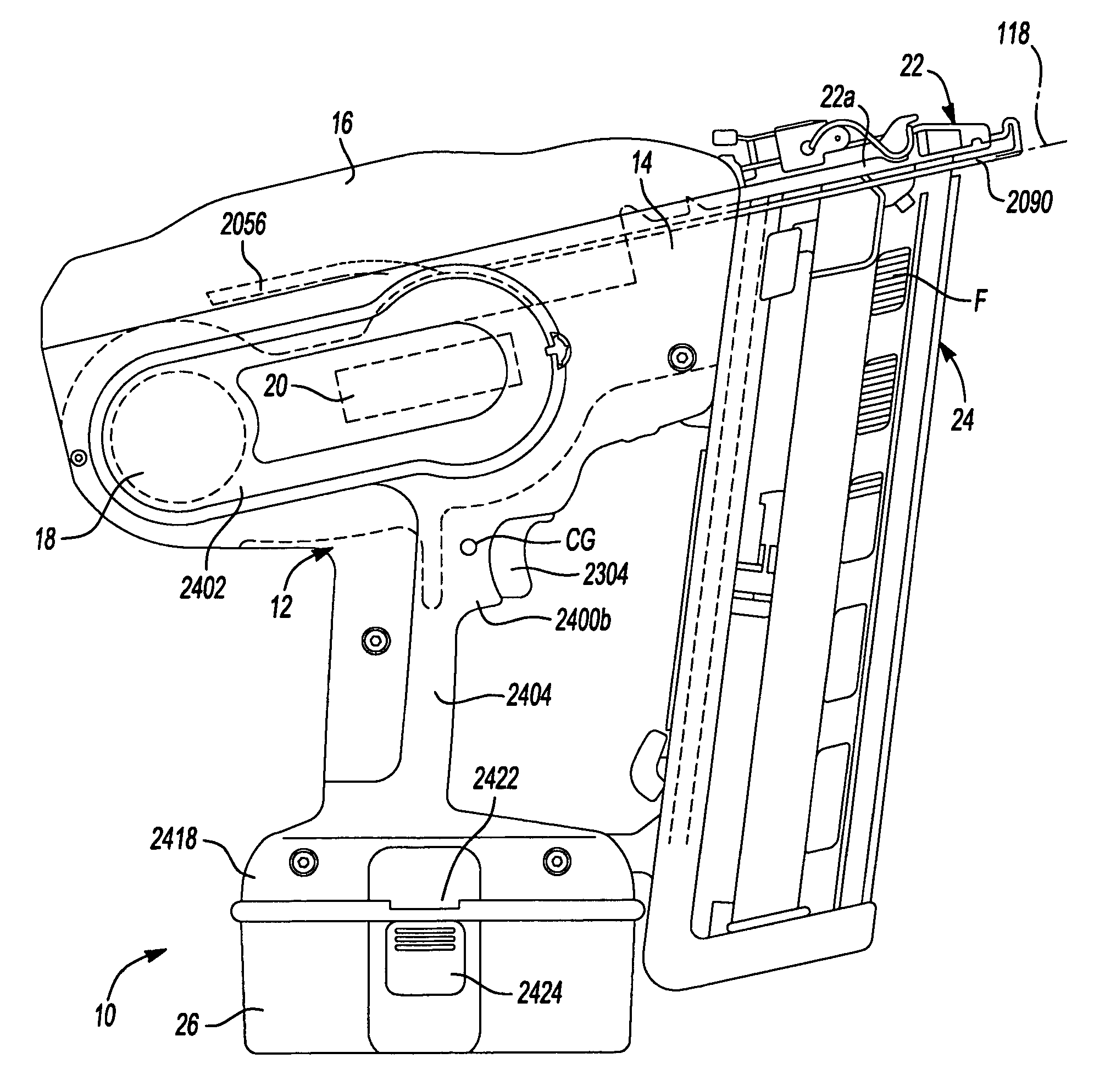
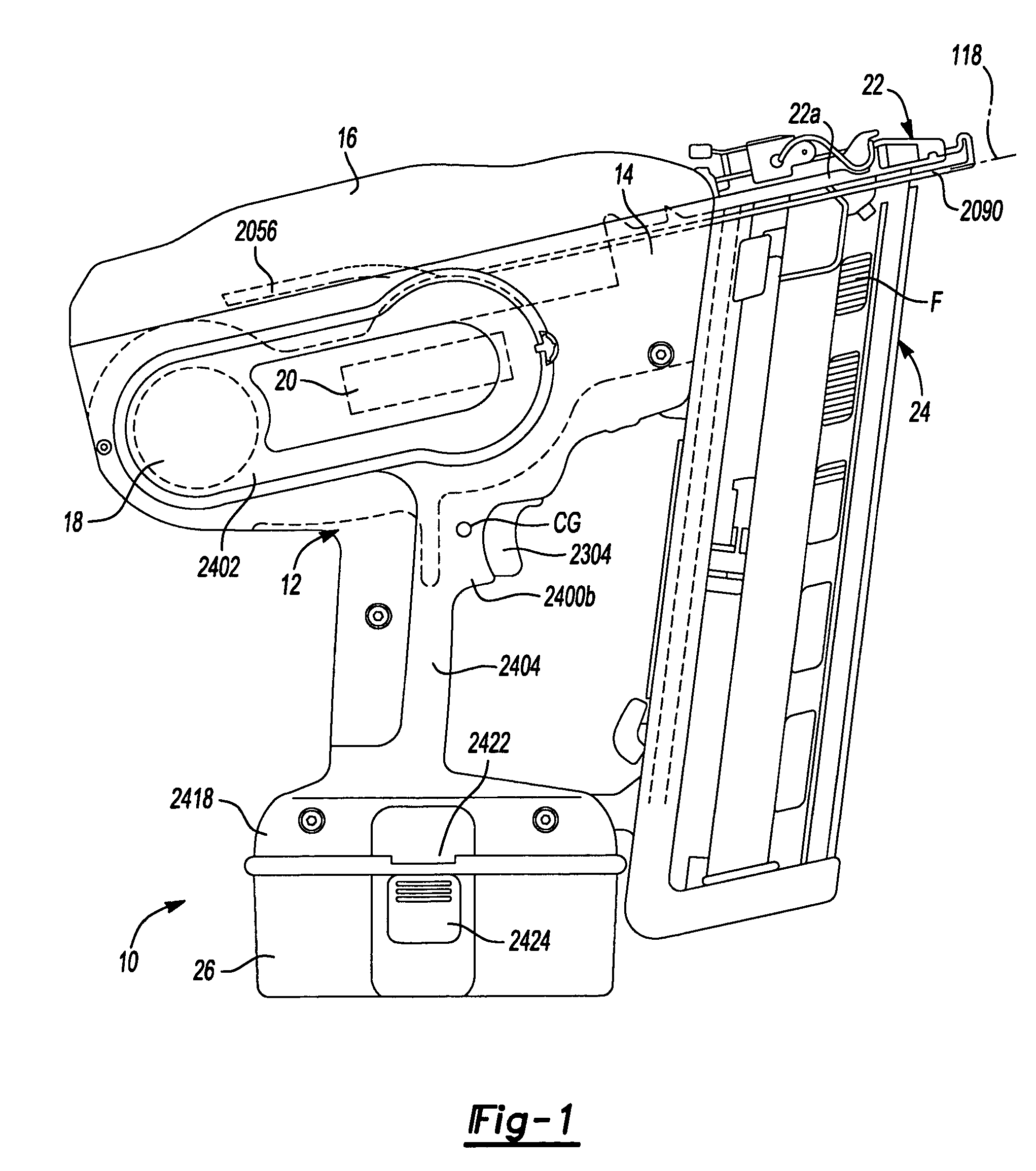
[0094]With reference to FIG. 1 of the drawings, a fastening tool constructed in accordance with the teachings of the present invention is generally indicated by reference numeral 10. The fastening tool 10 may include a housing assembly 12, a backbone 14, a backbone cover 16, an drive motor assembly 18, a control unit 20, a nosepiece assembly 22, a magazine assembly 24 and a battery pack 26. While the fastening tool 10 is illustrated as being electrically powered by a suitable power source, such as the battery pack 26, those skilled in the art will appreciate that the invention, in its broader aspects, may be constructed somewhat differently and that aspects of the present invention may have applicability to pneumatically powered fastening tools. Furthermore, while aspects of the present invention are described herein and illustrated in the accompanying drawings in the context of a nailer, those of ordinary skill in the art will appreciate that the invention, in its broadest aspects,...


PUM

PropertyMeasurementUnit
thicknessaaaaaaaaaa
velocityaaaaaaaaaa
angleaaaaaaaaaa

Abstract

A method for assembling an activation arm assembly for a power tool, such as a fastening tool or nailer. The method includes the mounting of various components of the activation arm assembly on pivot pins and positioning of a pair of arm members to load a spring that biases one of the arm members relative to another of the arm members.

Description

CROSS-REFERENCE TO RELATED APPLICATIONS[0001]This application claims priority to U.S. Provisional Patent Application Ser. No. 60 / 559,344 filed Apr. 2, 2004 entitled “Fastening Tool”.INTRODUCTION[0002]The present invention generally relates to a power tool, such as a fastening tool, and more particularly to a method for assembling an activation arm assembly for a power tool.[0003]Fastening tools, such as power nailers and staplers, are relatively common place in the construction trades. Often times, however, the fastening tools that are available may not provide the user with a desired degree of flexibility and freedom due to the presence of hoses and such that couple the fastening tool to a source of pneumatic power.[0004]Recently, several types of cordless nailers have been introduced to the market in an effort to satisfy the demands of modern consumers. Some of these nailers, however, are relatively large in size and / or weight, which renders them relatively cumbersome to work with...

Claims


Application Information

Patent Timeline
Patent Type & Authority Patents(United States)
IPC IPC(8): B23P11/00B25C5/16B25C1/06B25D1/00
CPCB25C1/06Y10T29/49904Y10T29/49826Y10T29/4984
Inventor KENNEY, JAMES J.SCHELL, CRAIG A.
Owner BLACK & DECKER INC
Why Eureka
Try Eureka