Bipolar clamp

Inactive Publication Date: 2007-01-23
ERBE ELEKTROMEDIZIN GMBH
View PDF18 Cites 132 Cited by
  • Summary
  • Abstract
  • Description
  • Claims
  • Application Information

AI Technical Summary

Benefits of technology

[0021]So that the clamp members are reliably electrically insulated from one another, the pivot joint employs as axis a peg that in one of the clamp members is seated in an insulating socket, in particular one made of ceramic. Seating in a ceramic socket offers the advantage that the pivot joint is particularly free of abrasion. Furthermore, ceramic has especially good electrically insulating properties. However, it is also possible for the insulating socket to be made of, for example, plas

Problems solved by technology

First, the current supply is provided at only one clamp member; more precisely, from a terminal attached to the handle device disposed at the proximal end of the clamp member the current is supplied by two wires that follow a common route approximately as far as the pivot joint between the two clamp members. From that point on, the wires run separately to the electrodes to which they are electrically connected. Although this makes manipulation of the clamp easier, the arrangeme

Method used


Image

  • Bipolar clamp
  • Bipolar clamp
  • Bipolar clamp

Examples


Example

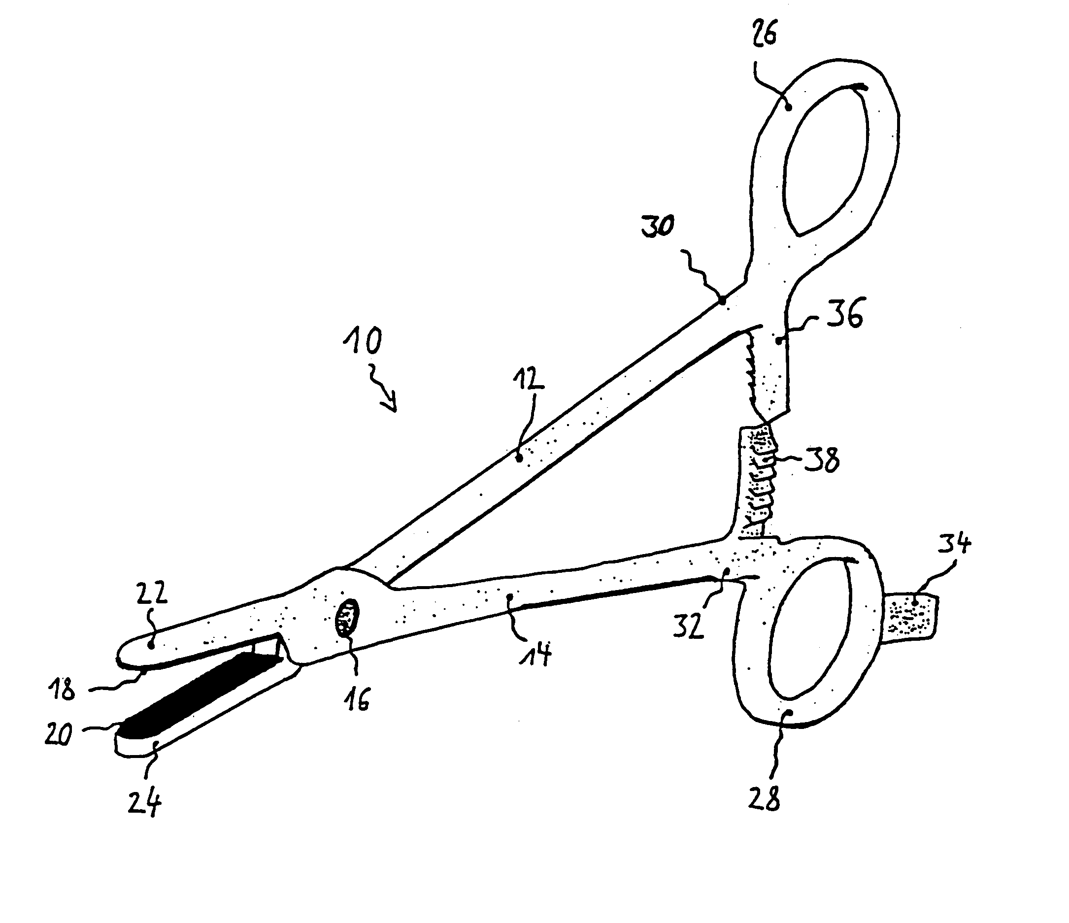
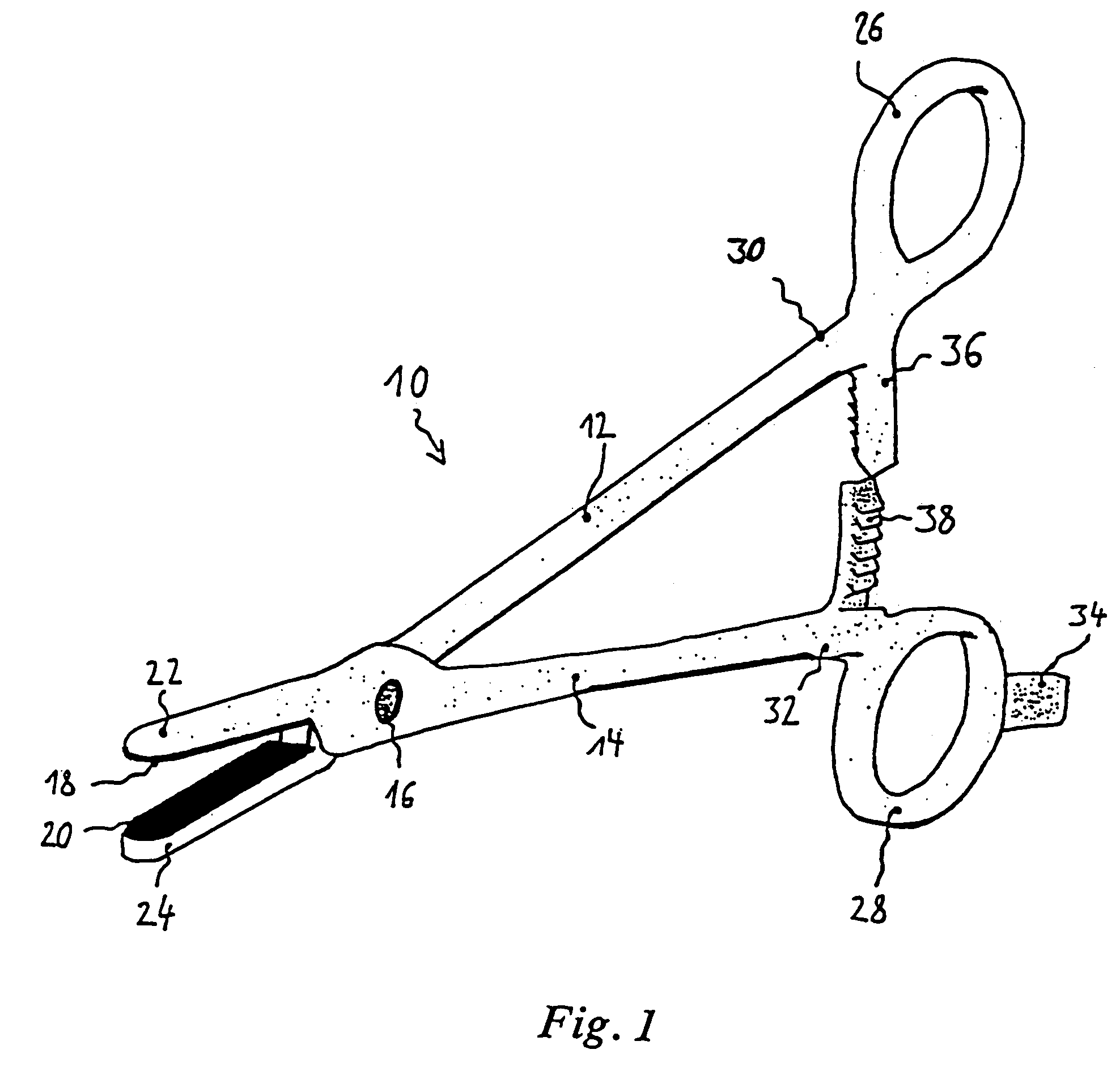
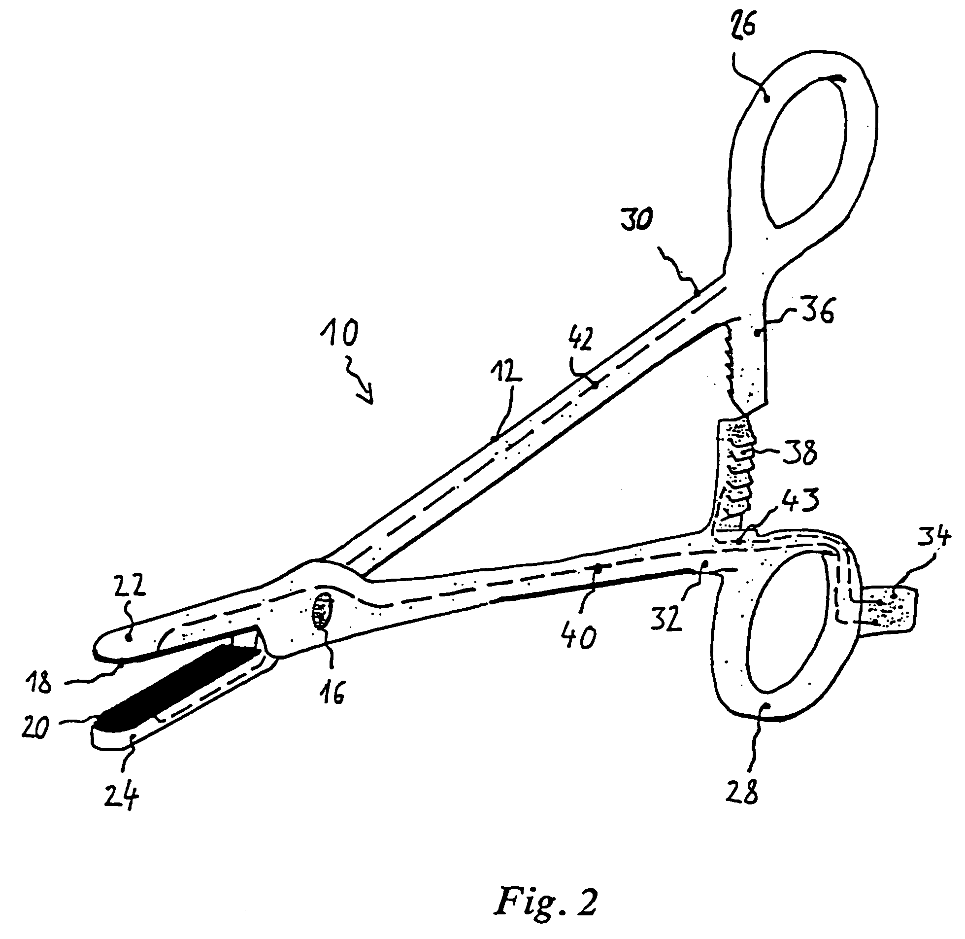
[0027]The bipolar clamp 10 shown in perspective in FIG. 1 comprises two clamp members 12 and 14. Each of the clamp members 12 and 14 is provided at its proximal end 30 or 32, respectively, with a handle device 26 or 28. The handle devices 26 and 28 are ring-shaped like the handles of scissors, so that they can easily be manipulated by an operator. The clamp members 12 and 14 are mechanically connected by a pivot joint 16 so that they can rotate with respect to one another. The pivot joint 16 is disposed near the distal ends 22 and 24 of the clamp members 12 and 14. At the distal ends 22 and 24 of the clamp members 12 and 14 electrically conductive electrode components 20 and 18, respectively, are attached. These are used both to grasp tissue and to pass a coagulation current through the tissue. For the latter purpose, they are preferably made of metal. At the handle device 28 of the clamp member 14 terminals of the current-supply means 34 are provided. To these are connected a HF ge...


PUM


Abstract

The invention relates to a bipolar clamp (10) comprising two scissor members (12, 14), which are joined together mechanically by means of an insulating screw or similar pivot joint (16) about which they can rotate with respect to one another, but are electrically insulated from one another,
    • electrode components (18, 20) at distal ends (22, 24) of the scissor members (12, 14) for grasping tissue and conducting an electrical current through the tissue to cause. coagulation,
    • handle devices (26, 28) at proximal ends (30, 32) of the scissor members (12, 14),
    • current-supply means (34, 40, 42) at the proximal end (32) of one scissor member (14)
    • ratchets (36, 38) between the pivot joint (16) and the proximal ends (32, 34) to lock, the scissor members (12, 14) to one another in a closed position.
In accordance with the invention the current-supply means (34, 40, 42) are so disposed, and the ratchets (36, 38) are so constructed, that current flow from the current-supply means (34, 40, 42) to the electrode components (18, 20) is possible only in the closed position. These measures make manipulation of the bipolar clamp (10) safer, because a coagulation current cannot flow until the clamp is in the closed position.

Description

RELATED U.S. APPLICATIONS[0001]This is the U.S. national phase of International Application No. PCT / EP02 / 06141 filed Jun. 4, 2002 and designating the U.S., the entire disclosure of which is incorporated herein by reference.FIELD OF THE INVENTION[0002]The invention relates to a bipolar clamp comprising two clamp members which are pivotally joined together and which, at the distal ends of the clamp members, are provided with electrode components for grasping tissue and conducting an electrical current through the tissue to cause coagulation.BACKGROUND OF THE INVENTION[0003]Such bipolar clamps are known, for example, from the PCT applications WO99 / 23933 and WO99 / 23959. They consist substantially of two clamp members joined together mechanically by means of an insulating screw or similar pivot joint, about which they can rotate with respect to one another, but are electrically insulated from one another. At the distal ends of the clamp members are provided electrode components for grasp...

Claims


Application Information

Patent Timeline
IPC IPC(8): A61B18/18A61B18/12A61B17/28A61B18/14
CPCA61B18/1442A61B2018/126A61B2018/00577A61B2017/2837
Inventor BARTEL, VOLKERHILLER, JURGEN
Owner ERBE ELEKTROMEDIZIN GMBH
Why Eureka
Try Eureka