Electromechanical protection switch

A technology for electromechanical protection and protection switches, applied in the direction of electric switches, emergency protection devices, circuits, etc., can solve the problems of separation current damage, limit the number of switching cycles of protection switches, increase the maintenance cost of protection switches, etc., to reduce burning loss, safety Effect of separation and minimization of transition resistance

Active Publication Date: 2019-03-08
LISA DRAXLMAIER GMBH
View PDF6 Cites 0 Cited by
  • Summary
  • Abstract
  • Description
  • Claims
  • Application Information

AI Technical Summary

Problems solved by technology

If such high load currents flow through the protective switch when the contacts are separated, the number of switching cycles of the protective switches currently used is limited due to their construction
The switching contacts of this protective switch, whose contacts usually consist of copper or silver, can only be separated a few times with a separating current of this magnitude, because the separating current usually causes serious damage on the switching contacts of the protective switch
The protective switch has to be replaced again after only a few switching cycles, which increases the maintenance costs of such protective switches

Method used


Image

  • Electromechanical protection switch
  • Electromechanical protection switch
  • Electromechanical protection switch

Examples


Embodiment Construction

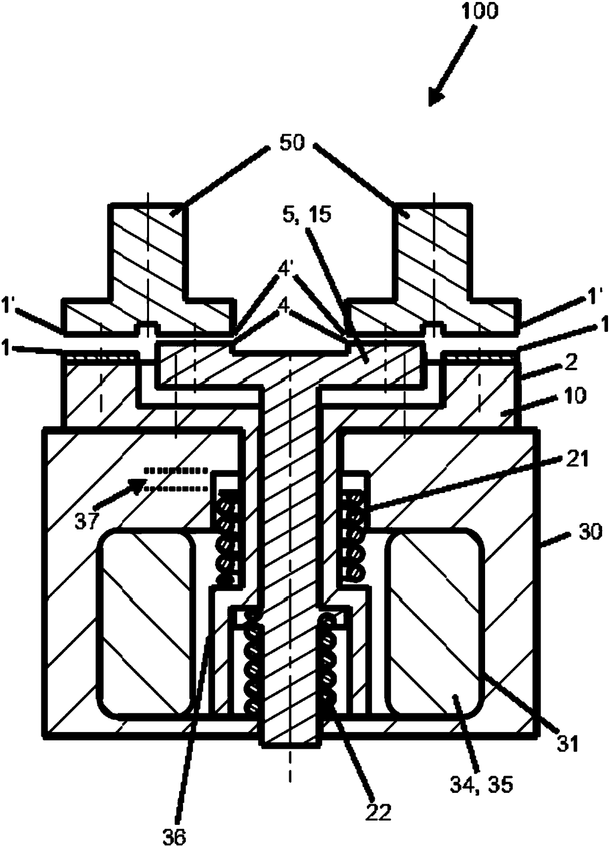
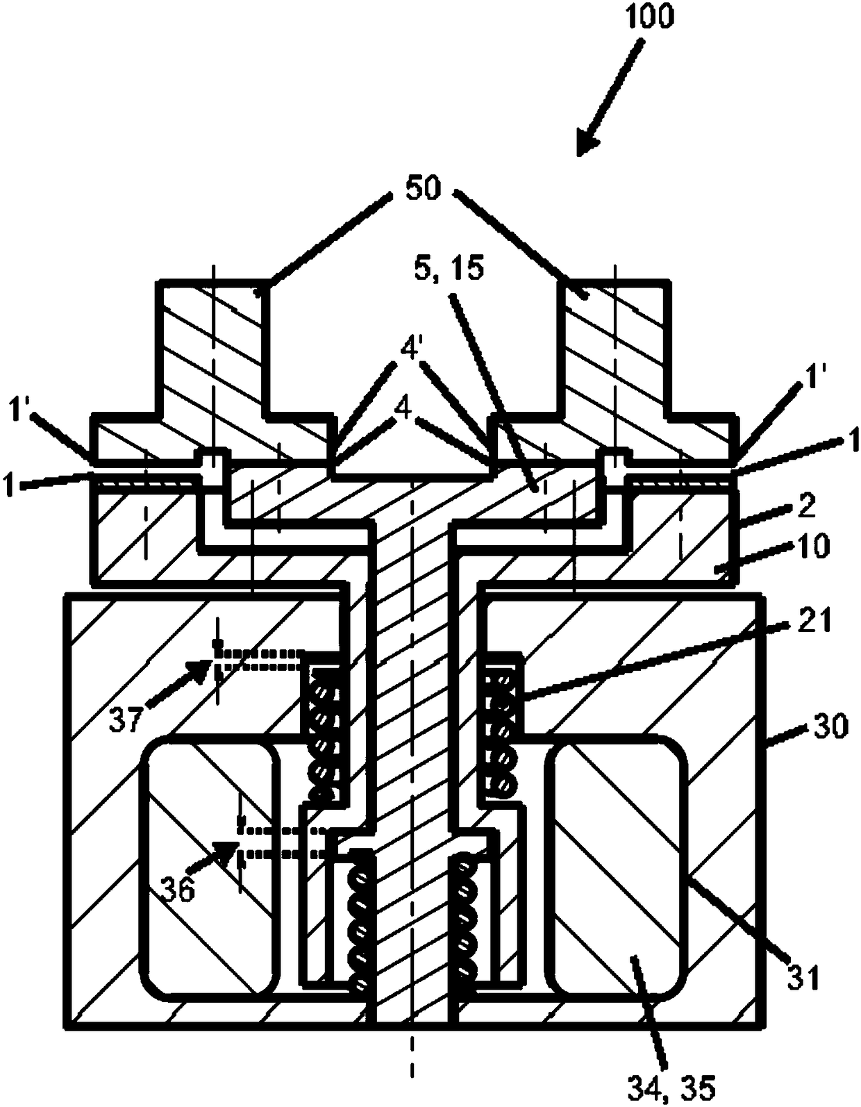
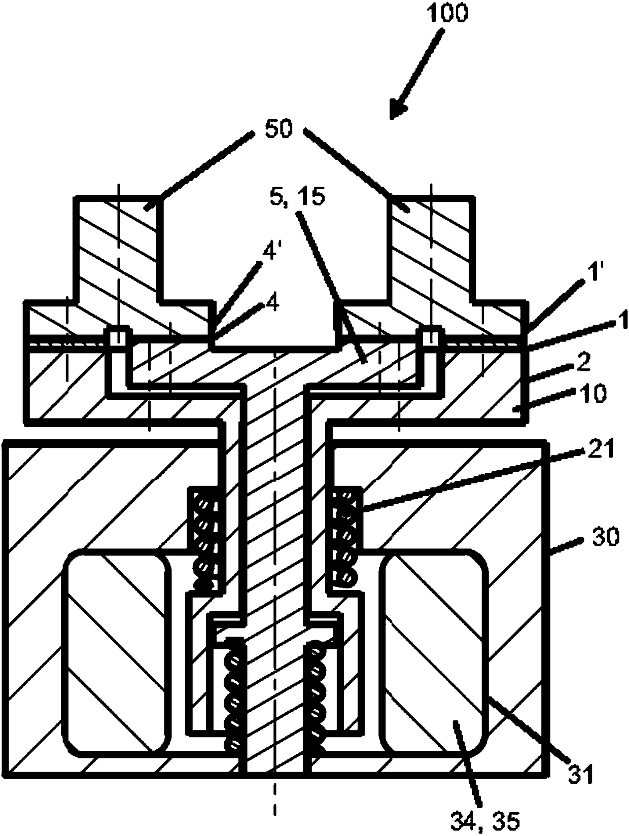
[0023] figure 1 A protective switch 100 is shown with two main contact pairs 1, 1', wherein the two main contacts 1 are arranged on the main contact bridge 2. The main contact pair 1, 1' is made of silver or a silver-containing material or is coated with silver or said silver-containing material. The protective switch 100 also comprises two secondary contact pairs 4, 4' having a material with a higher melting point than the main contact pair 1, 1'. The pair of secondary contacts 4, 4' is preferably made of or clad with tungsten. The two secondary contacts 4 are arranged on a secondary contact bridge 5 parallel to the main contact bridge 2 . The protective switch 100 also includes a first armature 10 for the movement of the main contact bridge 2 and a second armature 15 for the movement of the secondary contact bridge 5 . The armatures 10, 15 are formed such that the secondary contact pair 4, 4' opens after the main contact pair 1, 1' and closes before the main contact pair ...


PUM


Abstract

The invention relates to an electromechanical protection switch (100) with: - at least one main contact pair (1, 1'), wherein one main contact (1) is arranged on a main contact bridge (2) , - at least one pair of secondary contacts (4, 4') with a higher melting point material than the primary contact (1), wherein one secondary contact (4) is arranged in a On the secondary contact bridges (5) connected in parallel with the contact bridges (2), - the first armature (10) for the movement of the main contact bridge (2), - the second armature (for the movement of the secondary contact bridge (5) 15), wherein the armature (10, 15) is formed such that the pair of secondary contacts (4, 4') opens after the pair of primary contacts (1, 1') and before the pair of primary contacts (1, 1') closure.

Description

technical field [0001] The invention relates to electromechanical protective switches for separating high currents. Background technique [0002] Protective switches, also known as relays or protectors, are known in the prior art. The basic function of such protective switches is to switch high electrical powers in load circuits by means of relatively small currents, ie control currents. The current in the load circuit is here many times greater than the control current. [0003] A problem that arises in protective switches when switching on high power is that arcing can occur when the switching contacts are closed, which leads to wear of the switching contacts. In the protective switches known from the prior art, the switching contacts are made of copper or silver, for example. In particular, at high voltages and currents an unavoidable current flow occurs between the switching contacts to be separated. Usually, this arc is quenched by additionally using, for example, q...

Claims


Application Information

Patent Timeline
Patent Type & Authority Patents(China)
IPC IPC(8): H01H50/62H01H1/20
CPCH01H1/20H01H50/62H01H1/2025H01H50/541H01H50/546H01H50/56H01H51/20H01H2235/01
Inventor 马可·费勒默彼得·法拉特迈尔克里斯蒂安·格鲁伯克里斯托弗·马赫纳
Owner LISA DRAXLMAIER GMBH
Why Eureka
Try Eureka