Airbag apparatus

a technology of airbags and airbags, which is applied in the direction of pedestrian/occupant safety arrangements, vehicular safety arrangements, vehicle components, etc., can solve the problems of dislodging the connecting port portion from the inflator, the downstream side of the gas in the gas supply passage portion is quickly deployed and inflated thick,

Inactive Publication Date: 2007-01-30
TOYODA GOSEI CO LTD
View PDF8 Cites 12 Cited by
  • Summary
  • Abstract
  • Description
  • Claims
  • Application Information

AI Technical Summary

Benefits of technology

[0016]The invention was made to solve the problems and an object of the invention is to provide an airbag apparatus which can perform a suitable deployment mode in accordance with its installation position, more specifically, to provide a head protecting airbag which can make a predetermined parallel cell between the upstream side and the downstream side of the inflating gas in the gas supply passage portion deploy quickly and inflate thick.
[0030]By this structure, while the inflating gas, which flows from the position near above the upstream side parallel cell to the position near above the downstream side parallel cell via above the quick deployable cell, attempts to flow from the inlet port in the upper portion of the upstream side parallel cell into the upstream side parallel cell, the gas tends to flow to the inlet port of the quick deployable cell by virtue of inertial force. Then, the inflating gas, which is introduced into the quick deployable cell from the inlet port thereof, flows to a lower end side of the quick deployable cell so as to be guided by the horizontal portion and the vertical portion of the downstream side extending partitioning portion. Furthermore, since the quick deployable cell is closed at the lower end thereof by the upstream side extending portion, the lower edge portion of the peripheral portion and the vertical portion of the downstream side extending portion, the quick deployable cell deploys quickly by the inflating gas flowing to the lower end side of the quick deployable cell to thereby complete the thick inflation thereof.
[0031]On the other hand, in the upper stream side parallel cell which is adjacent to the quick deployable cell, since the inflating gas, which flows in from the inlet port of the upstream side parallel cell, flows to the inlet port of the quick deployable cell to thereby reduce the amount of the inflating gas which flows toward the lower end side of the upstream side parallel cell, the timing of completion of thick inflation is delayed to a later time than the quick deployable cell.
[0034]Consequently, in the head protecting airbag according to the invention, the predetermined cell from the upstream side to the downstream side of the inflating gas in the gas supply passage portion, that is, the quick deployable cell can be deployed quickly to be inflated thick.

Problems solved by technology

Namely, with the conventional head protecting airbag, there has been a problem with making the predetermined parallel cell between the upstream side and the downstream side of the gas in the gas supply passage portion is deployed quickly and inflated thick.
However, with the connecting construction between the connecting port portion and the inflator by making use of only the clamp, in case the output of the inflator increases as the volume of the airbag increases, there is caused a risk that the connecting port portion is dislodged from the inflator when the inflator is activated, and there still remains a room for improvement in increasing the connection strength.

Method used


Image

  • Airbag apparatus
  • Airbag apparatus
  • Airbag apparatus

Examples


first embodiment

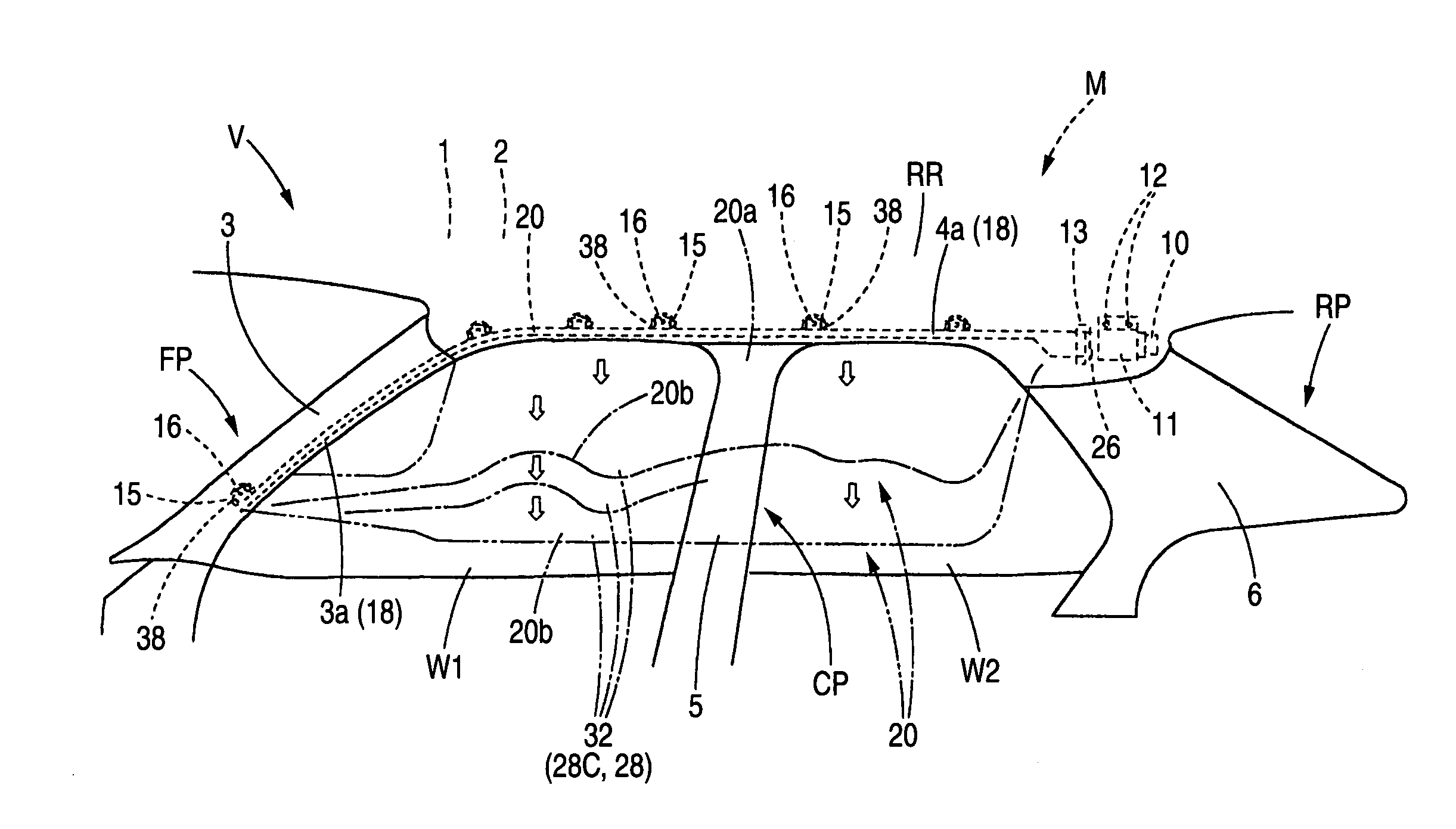
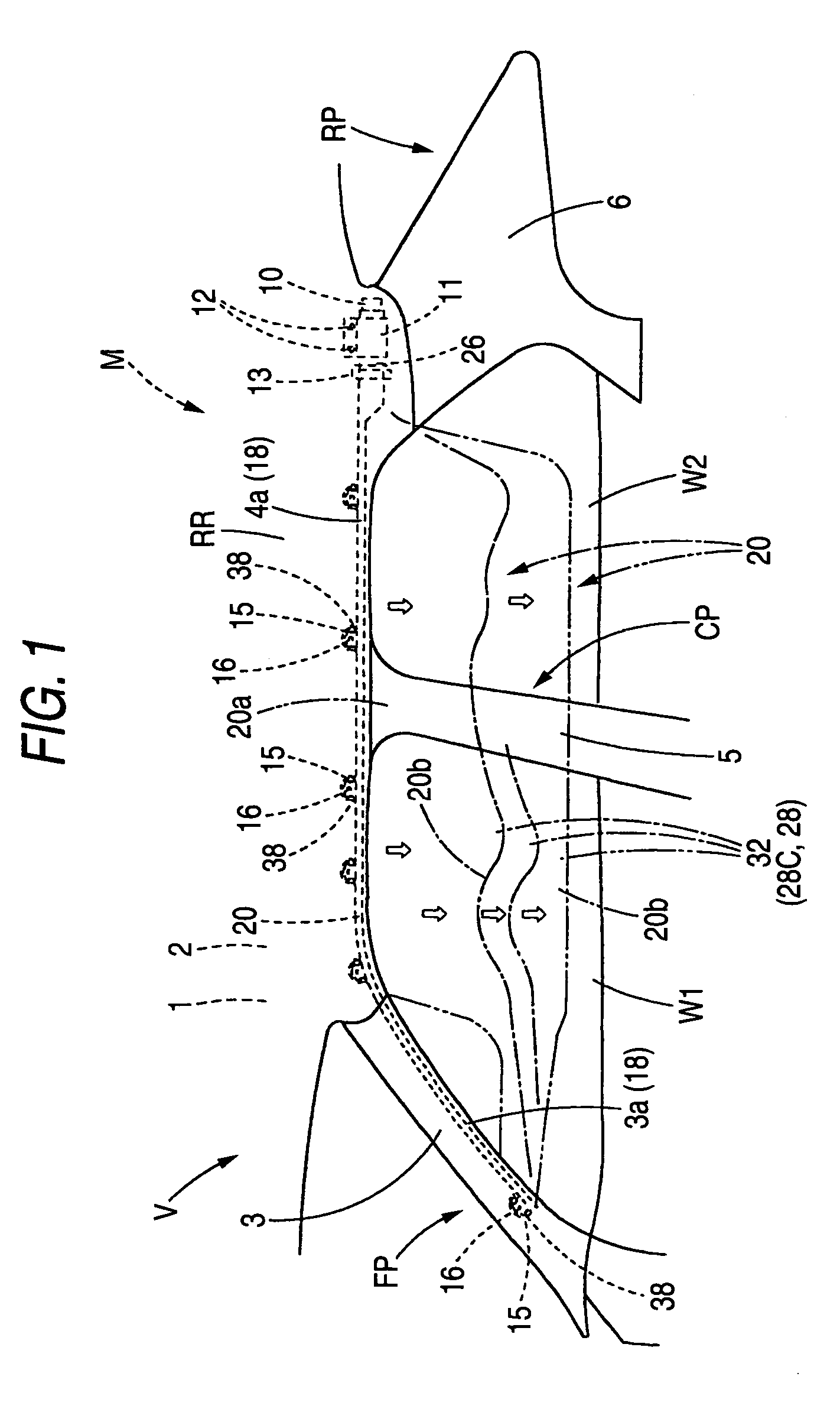
[0055]Hereinafter, to describe a first embodiment of the invention based on the drawings, as shown in FIGS. 1, 4, a head protecting airbag 20 of the first embodiment is such as to be used in a head protecting airbag apparatus M1 that is to be installed on a vehicle V and is folded up to be housed in a range extending from a position of a front pillar portion FP which faces upper parts of windows W1, W2 (side windows) of the vehicle V to a position on a roof side rail portion RR which is near above a rear pillar portion RP so as to cover the windows W1, W2 when the airbag deploys and inflates downward completely. Note that this vehicle V is constructed so as to have a center pillar portion CP provided between the front pillar portion FP and the rear pillar portion RR so as to extend substantially along the vertical direction, and that the airbag 20 is designed to cover the windows W1, W2, as well as an interior side of a pillar garnish 5 of the center pillar portion CP.

[0056]As shown...

second embodiment

[0090]Hereinafter, a second embodiment of the invention will be described based on the drawings. The second embodiment will be described by taking a head protecting airbag apparatus M2 as shown in FIG. 6 as an airbag apparatus to which the invention can be applied. The head protecting airbag apparatus M2 is such as to be installed on a vehicle V shown in FIG. 6 and is housed at a housing part P which is formed in parts of a front pillar portion FP and a roof side rail portion RR which face upper edges of doors, windows W1, W2 and a rear pillar portion RP which are inside a compartment. Note that this vehicle V is constructed to have a center pillar provided between the front pillar portion FP and the rear pillar portion RP so as to extend substantially along a vertical direction.

[0091]The head protecting airbag apparatus M2 is, as shown in FIG. 6 configured to include an inflator 108, attachment brackets 109, 139, 145, attachment bolts 110, 142, an airbag 115 and a protecting cover ...

third embodiment

[0127]To describe an third embodiment of the invention below based on the drawings, as shown in FIG. 12, an airbag apparatus M3 of the third embodiment is a head protecting airbag apparatus M3 which is configured to include a head protecting airbag 220 which can cover windows (side windows) W1, W2, W3 of a vehicle V when the airbag 220 deploys and inflates completely. Upper parts of the windows W1, W2, W3 functioning as a housing part U, the airbag 220 is folded up to be housed in a range from a front pillar portion FP to a position on a roof side rail portion RR which is near above a rear pillar portion RP. Note that this vehicle is made as a vehicle of a three-row-seat type in which two intermediate pillar portions P1, P2 which extend in a substantially vertical direction are provided between the front pillar portion FP and the rear pillar portion RP and seats are provided, respectively, at interior sides of the respective windows W1, W2, W3, and the airbag 220 is designed to cove...


PUM


Abstract

A head protecting airbag is folded up to be housed at an upper part of a window of a vehicle so as to be deployed and inflated downward from the upper part of the window so as to cover an interior side of the window. In the airbag, a plurality of parallel cells adapted to be deployed and inflated by an inflating gas introduced thereinto are provided in parallel with each other below a gas supply passage portion in which the inflating gas flows along a longitudinal direction. In a cell of the parallel cells so provided which is required to deploy quickly, of front and rear partitioning portions, a partitioning portion situated at an upstream side of the gas flowing in the gas supply passage portion is provided such that an end thereof which extends upward from a lower edge portion is disposed so as to form an inlet port between a distal end of a horizontal portion of a downstream side partitioning portion and itself.

Description

BACKGROUND OF THE INVENTION[0001]1. Field of the Invention[0002]The present invention relates to an airbag apparatus comprising an airbag which is attached to a housing part of a vehicle. Specifically, the present invention relates to a head protecting airbag which is configured so as to be folded up to be housed at an upper part of a window of the vehicle in a state that the periphery of the airbag is covered by a protecting cover of a synthetic resin after folded up so as to deploy and inflate to protrude downward from the housing part to cover an interior side of the window when an inflating gas is introduced thereinto.[0003]2. Related Art[0004]Conventionally, a head protecting airbag which completes its inflation so as to cover an interior side of a window of a vehicle is made to comprise a gas introducing portion which inflates so as to separate an interior wall portion and an exterior wall portion from each other by allowing an inflating gas to be introduced thereinto and a no...

Claims


Application Information

Patent Timeline
Patent Type & Authority Patents(United States)
IPC IPC(8): B60R21/16
CPCB60R21/213B60R21/2338B60R21/232B60R2021/23386
Inventor KINO, MASAOYAMAMOTO, TADASHIITO, MICHIYASUIKEDA, TAKANOBUYAMADA, TADASHI
Owner TOYODA GOSEI CO LTD
Why Eureka
Try Eureka