Bumper system with energy absorber

a bumper system and energy absorber technology, applied in the field of bumper systems, can solve the problems of requiring the downtime of the molding machine, requiring time and labor to change molds, and increasing the cost of each additional mold

Inactive Publication Date: 2007-02-06
NETSHAPE INT LLC
View PDF140 Cites 30 Cited by
  • Summary
  • Abstract
  • Description
  • Claims
  • Application Information

AI Technical Summary

Problems solved by technology

Each additional mold is expensive, because they are relatively large and long.
Further, it takes time and labor to change molds, and requires downtime of the molding machine.

Method used


Image

  • Bumper system with energy absorber
  • Bumper system with energy absorber
  • Bumper system with energy absorber

Examples


Embodiment Construction

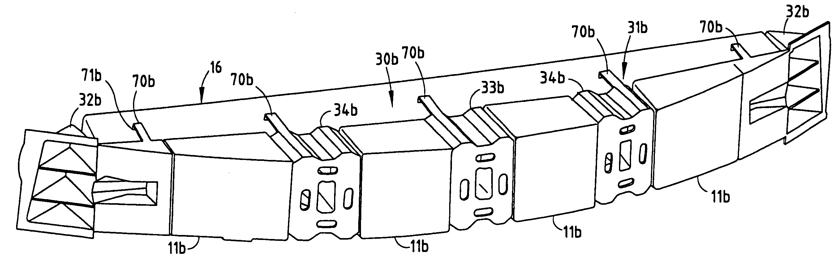
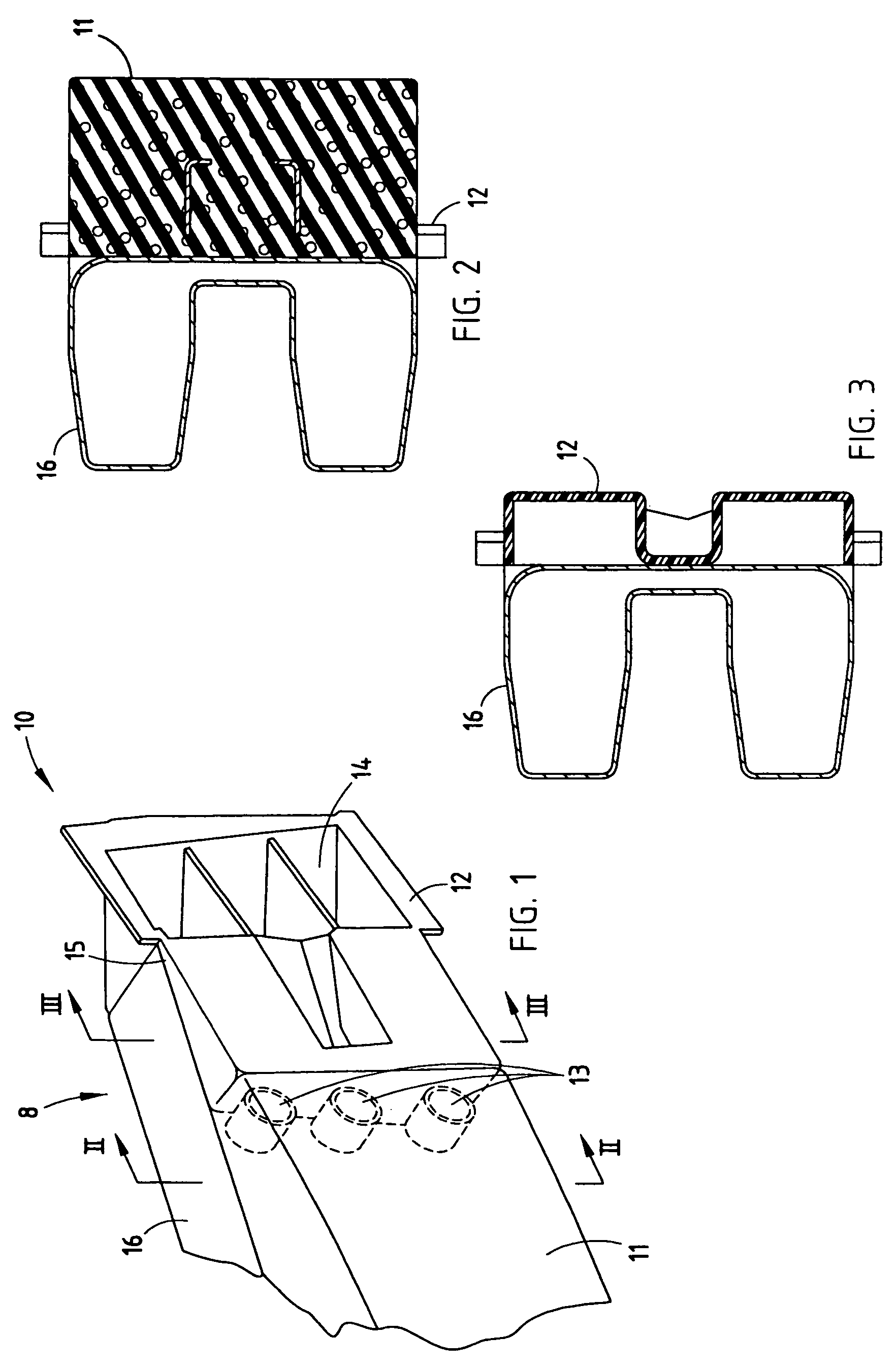
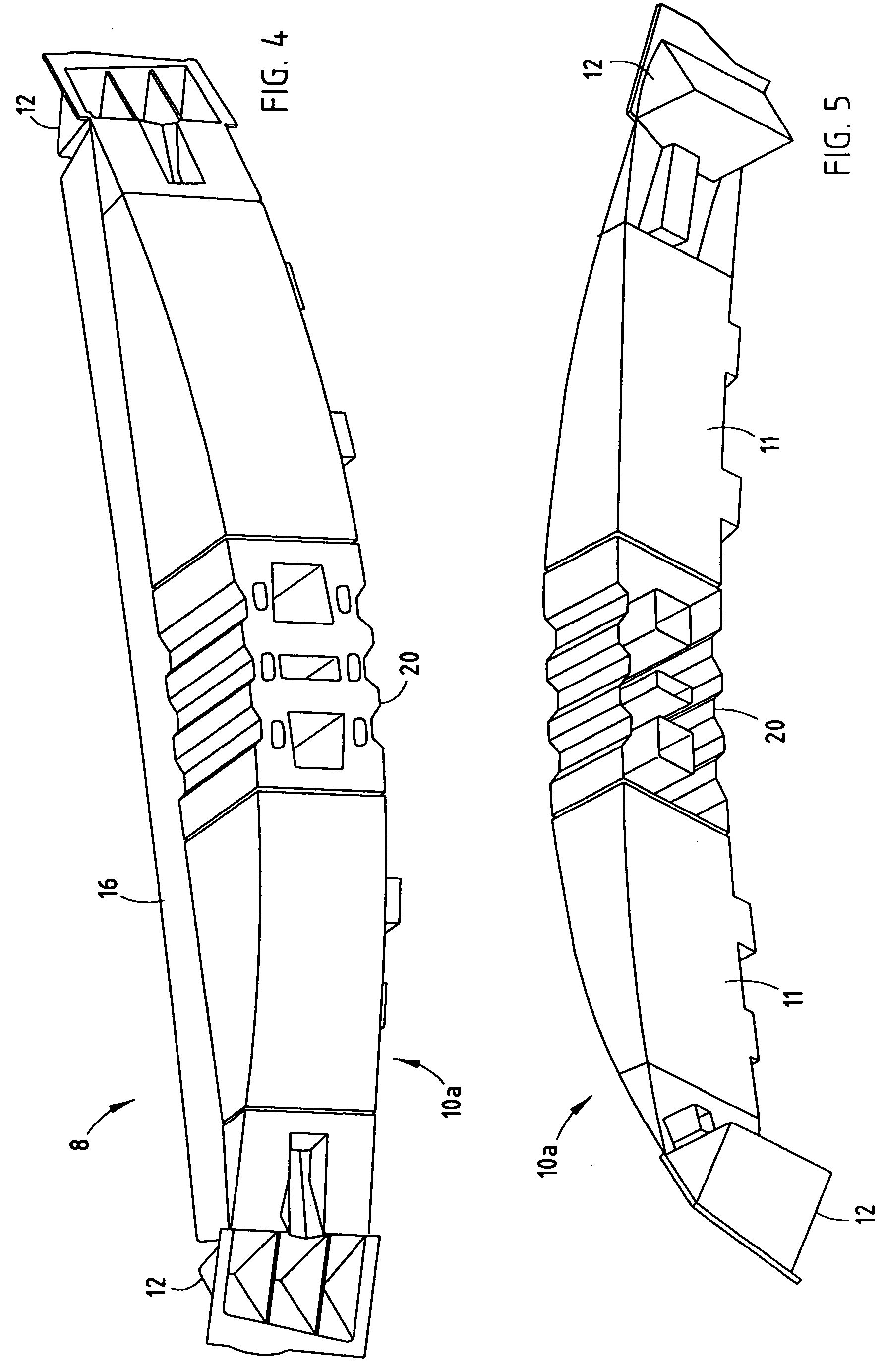
[0021]A bumper system 8 (FIG. 1) includes a bumper beam 16 having a face and ends, and an energy absorber 10 mounted on the face. The energy absorber 10 has a center-located foam piece 11 engaging the face and an injection-molded end piece 12 securely attached to each end of the foam piece and also engaging the face. By this arrangement, the energy absorber 10 is a single unit that can be handled and attached to the bumper beam 16. Also, the energy absorber 10 can include different end pieces while still using the same foam piece, or alternatively, the energy absorber can include different center pieces while using the same injection-molded non-foam end pieces. Thus, the present inventive concepts provide the advantages of smaller molding dies for molding the injection-molded non-foam components. This is important because molding dies for injection-molded components are considerably more expensive than molding dies for foam components. At the same time, the present methods and appar...


PUM


Abstract

A bumper system includes a bumper beam having a face and ends, and an energy absorber mounted on the face. The energy absorber has a one-piece injection-molded non-foam piece with box sections and interconnecting straps, and a one-piece or multi-piece foam component securely insert-molded onto the injection-molded non-foam piece. Different foam molds can be used to form differently shaped front surfaces on the foam component. By this arrangement, different energy absorbing systems are provided for vehicles, such as to satisfy the need for different styling and shapes, while still using the same non-foam piece. By this arrangement, the energy absorber is a single unit that can be handled and attached to the bumper beam. At the same time, capital investment in molding dies and tooling is reduced.

Description

CROSS-REFERENCE TO RELATED APPLICATIONS[0001]This application is a continuation of commonly assigned, co-invented application Ser. No. 10 / 694,278 filed on Oct. 27, 2003, entitled BUMPER SYSTEM WITH ENERGY ABSORBER, now U.S. Pat. No. 7,052,056, which is a divisional of commonly assigned, co-invented application Ser. No. 10 / 163,586 filed on Jun. 6, 2002, entitled BUMPER WITH INTEGRATED FOAM AND NON-FOAM COMPONENTS, now U.S. Pat. No. 6,672,635.BACKGROUND[0002]The present invention relates to vehicle bumper systems having an energy absorber on a bumper beam, and more particularly relates to a bumper system having an energy absorber on the beam that is adapted to provide different levels of energy absorption in selected areas but further adapted to take maximum advantage of mass production.[0003]Vehicle bumper systems often include a bumper beam for strength and a mounted energy absorber to help absorb energy and distribute stress across the bumper beam during impact. However, each diffe...

Claims


Application Information

Patent Timeline
Patent Type & Authority Patents(United States)
IPC IPC(8): B60R19/03B60R19/04B60R19/18
CPCB29C44/08B60R19/18B60R19/04B60R2019/1813Y10T29/49622B60R2019/186B60R2019/1866B60R2019/1873Y10T29/4998B60R2019/1846
Inventor WEISSENBORN, MARKEVANS, DARINWEYKAMP, ROBERTPOWELL, DAVID
Owner NETSHAPE INT LLC
Why Eureka
Try Eureka