
Digital system and method for testing analogue and mixed-signal circuits or systems

a digital system and mixed signal technology, applied in the direction of analog circuit testing, error detection/correction, instruments, etc., can solve the problems of low-cost automatic test equipment, high cost of electronic products, and high cost of testing time, so as to achieve low-cost effect of time-consuming and costly mixed signal circuits

Inactive Publication Date: 2007-02-06
ATEEDA
View PDF8 Cites 2 Cited by
  • Summary
  • Abstract
  • Description
  • Claims
  • Application Information

AI Technical Summary

Benefits of technology

"The patent is about a method for optimizing a digital test signal for testing analog or mixed signal circuits. The method involves applying a plurality of different digital inputs to a fault-free circuit and a faulty circuit, monitoring the output responses, and using the output responses to identify potential defects in the circuit. The method aims to identify and design an optimal test signal that can detect faults quickly and accurately during manufacture. The method can be easily automated and can be used in real-time testing during manufacture. The technical effect of the patent is to provide a reliable and efficient method for testing analog or mixed signal circuits."

Problems solved by technology

The cost of an electronic product is related to the cost of the tests and the time necessary to generate and apply these.
In terms of testing, mixed analogue and digital circuits, so called mixed-signal circuits, can be particularly time consuming and costly.
Indeed, it has been reported that one of the greatest challenges in the coming years is the development of low-cost automatic test equipment for testing mixed-signal integrated circuits, see “International Technology Roadmap for Semiconductors”, 1999, published by the Semiconductor Industry Association (SIA).
Therefore the amount of information to be processed during testing is potentially very large.
This inability to discriminate is made worse by the greater functionality and complexity of even the simplest analogue circuit, particularly if input signals are limited in complexity or time duration.
In addition, because output signals are analogue, there can be no ideal performance from a completely “correct” circuit.
All of these features make the testing of analogue circuits somewhat problematic.
One of the main problems with testing mixed-signal circuits is the need for separate analogue and digital test instruments.
Existing digital approaches for testing mixed-signal systems have had limited success.
However, despite extensive research, a satisfactory solution to the problem of how to test analogue and / or mixed-signal circuits using a digital signal has not been found.

Method used


Image

  • Digital system and method for testing analogue and mixed-signal circuits or systems
  • Digital system and method for testing analogue and mixed-signal circuits or systems
  • Digital system and method for testing analogue and mixed-signal circuits or systems

Examples


Embodiment Construction

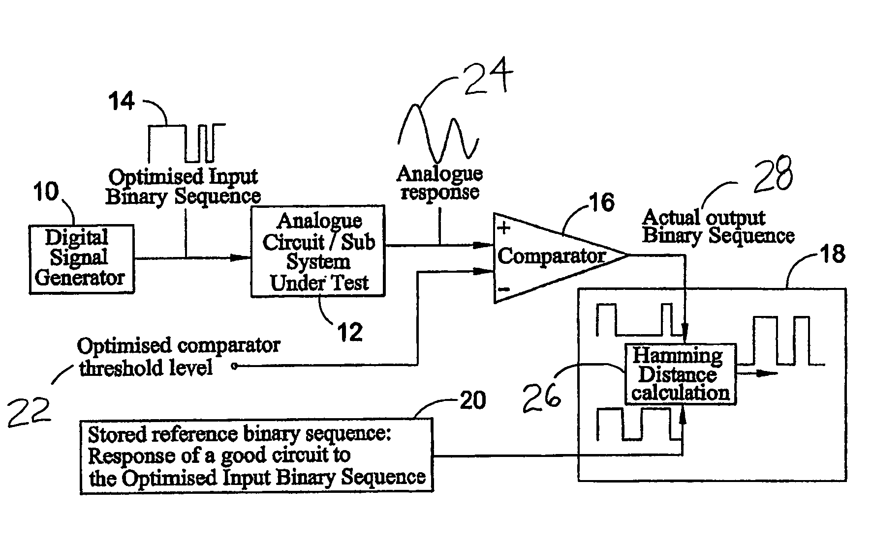
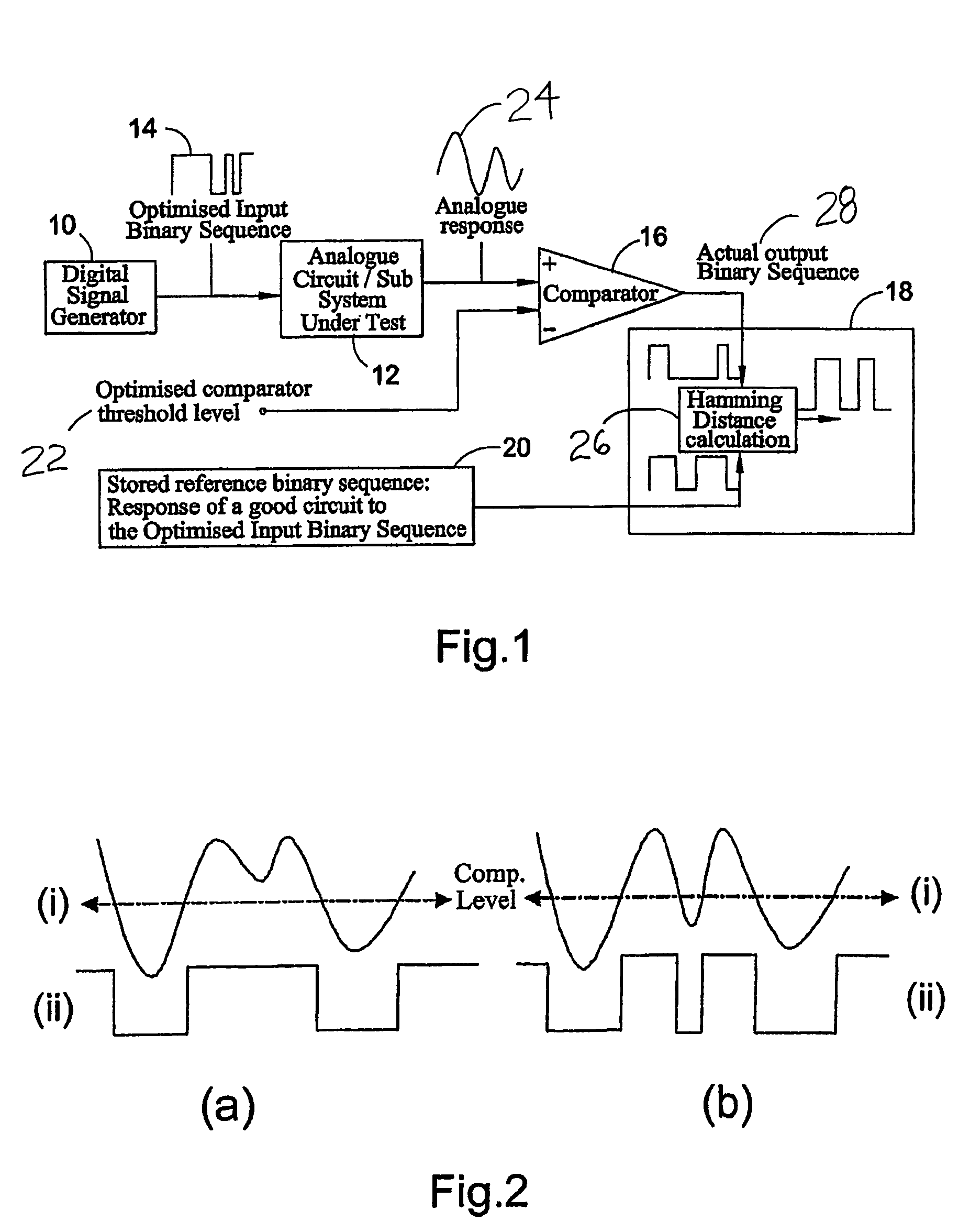
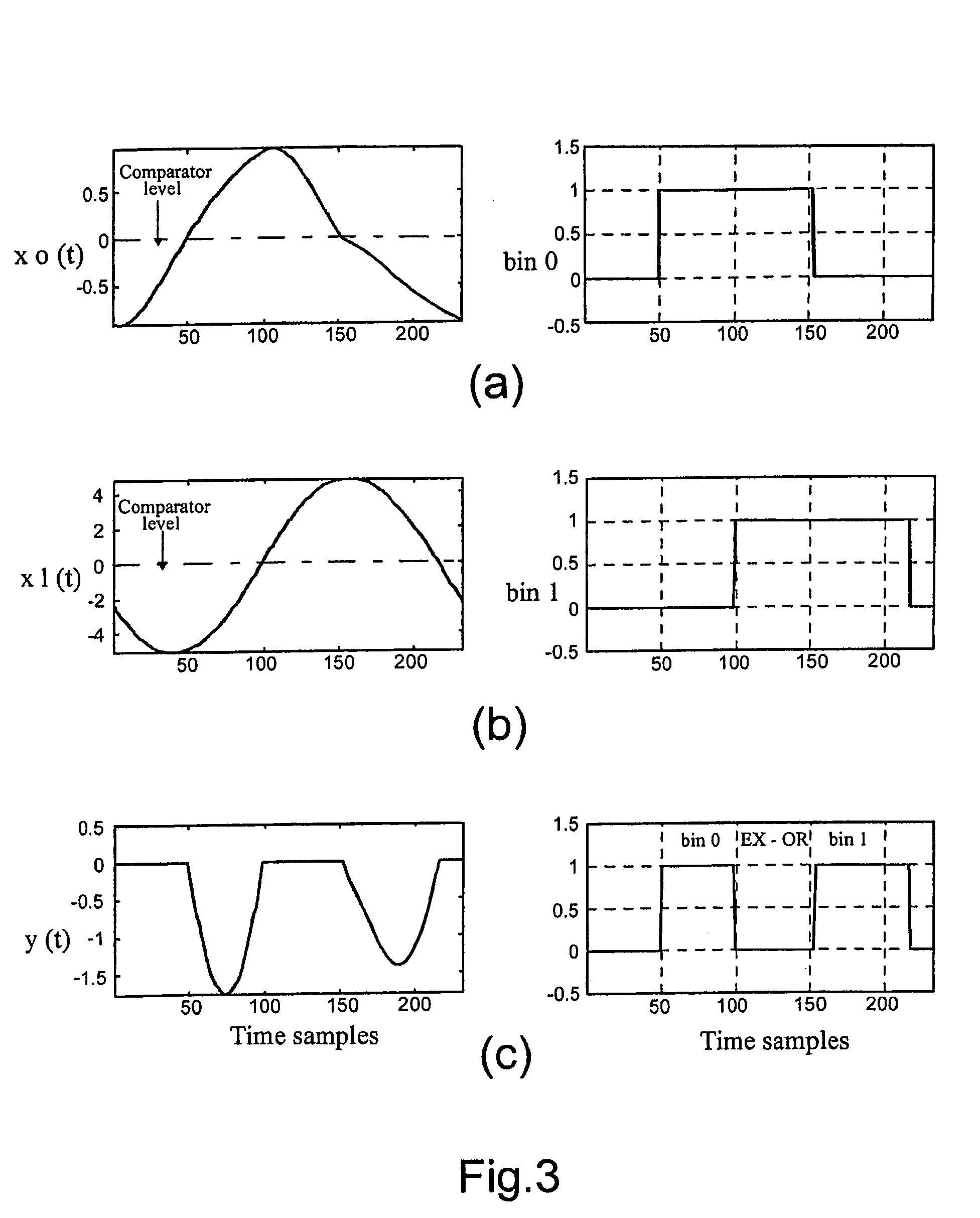
[0067]The aim of mixed-signal testing is to detect manufacturing defects. Integrated circuits can have two types of permanent faults, namely catastrophic or parametric faults. A catastrophic fault is one in which the component is destroyed, for example by virtue of a short circuit, an open circuit or a topological change. With parametric faults, the component continues to function, but outside the nominal tolerance band. Examples of faults that have to be detected include: short circuit, open circuit, positive deviation from fault free behaviour and negative deviation. By choosing a suitable binary test signal, these can be identified.

[0068]In accordance with the present invention, two modes of operation have to be carried out in order to test mixed-signal circuits. Firstly, a test development mode is conducted to determine the optimum test signal. When a suitable test signal is identified, a test application mode uses that optimised signal to test circuits. This is done by applying...


PUM


Abstract

A method of optimising a digital test signal for testing an analogue or mixed-signal circuit comprising determining a measure, for example a figure of merit, that is indicative of differences between the output of a fault free and the output of a known faulty circuit in response to an applied digital input signal. The digital input signal is then varied and another figure of merit is calculated for the fault free and the known faulty circuit for the new input signal. This is repeated a number of times, the digital input signal being varied each time. An optimum test signal is selected based on the determined figures of merit.

Description

FIELD OF THE INVENTION[0001]The present invention relates to a digital system and method for testing analogue and mixed-signal (analogue and digital) circuits or systems.BACKGROUND OF THE INVENTION[0002]Testing of circuits is an essential step in the manufacture of high quality and reliable electronic products. The cost of an electronic product is related to the cost of the tests and the time necessary to generate and apply these. In terms of testing, mixed analogue and digital circuits, so called mixed-signal circuits, can be particularly time consuming and costly. Indeed, it has been reported that one of the greatest challenges in the coming years is the development of low-cost automatic test equipment for testing mixed-signal integrated circuits, see “International Technology Roadmap for Semiconductors”, 1999, published by the Semiconductor Industry Association (SIA).[0003]Analogue signals are continuous as a function of both time and amplitude. Therefore the amount of informatio...

Claims


Application Information

Patent Timeline
Patent Type & Authority Patents(United States)
IPC IPC(8): G01R31/28G06F11/00G01R31/316G01R31/3167G01R31/3183
CPCG01R31/3167G01R31/318371G01R31/318342
Inventor HAMILTON, DAVID JAMESSTIMPSON, BRIAN PHILIPBEKHEIT, MAHMOUD ALI MOUSA
Owner ATEEDA
Learn More