

High temperature end fitting and method of use
- Summary
- Abstract
- Description
- Claims
- Application Information
AI Technical Summary
Benefits of technology
Problems solved by technology
Method used
Image

Examples
Embodiment Construction
[0020]The following disclosure provides many different embodiments, or examples, for implementing different features of the invention. Specific examples of components, signals, messages, protocols, and arrangements are described below to simplify the present disclosure. These are, of course, merely examples and are not intended to limit the invention from that described in the claims. Well-known elements are presented without detailed description in order not to obscure the present invention in unnecessary detail. For the most part, details unnecessary to obtain a complete understanding of the present invention have been omitted inasmuch as such details are within the skills of persons of ordinary skill in the relevant art.
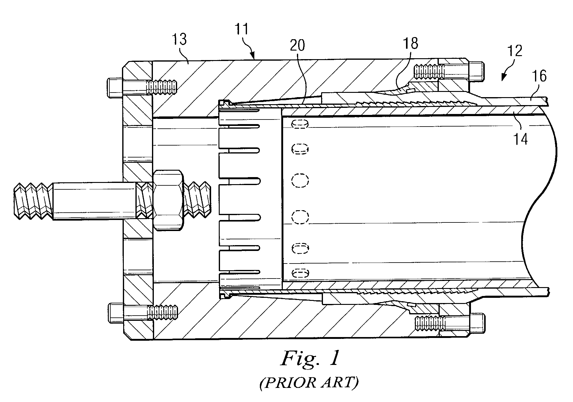
[0021]Referring now to FIG. 1 of the drawings, there is illustrated a prior art end fitting designated 11 as disclosed, for example, in U.S. Pat. No. 5,639,128 incorporated herein by reference and available from commercial sources such as Wellstream, Inc. of Panam...
PUM
| Property | Measurement | Unit |
|---|---|---|
| Temperature | aaaaa | aaaaa |
| Flexibility | aaaaa | aaaaa |
| Deformation enthalpy | aaaaa | aaaaa |
Abstract
Description
Claims
Application Information