Method and apparatus for a two-chip cinematography camera

Inactive Publication Date: 2007-02-13
TELEDYNE DIGITAL IMAGING INC
View PDF39 Cites 17 Cited by
  • Summary
  • Abstract
  • Description
  • Claims
  • Application Information

AI Technical Summary

Benefits of technology

[0012]An advantage of the present invention is that it replaces a film cameras with an electronic camera.
[0013]These and other advantages are achieved in an a camera that includes a first sensor disposed to image light that propagates along a reflected axis and a second sensor disposed to image light that propagates along a direct axis. The camera also includes a rotatable structure disposed to define a rotation plane that is oblique to both the reflected axis and the direct axis. The rotatable structure is one of a first structure and a second structure. The first structure includes a first transmission sector, a first reflection sector disposed adjacent to the first transmission sector, a second transmission sector disposed adjacent to the first reflection sector and a second reflection sector disposed adjacent to the second transmission sector. The second structure includes a first reflection sector, a first opaque sector disposed adjacent to the first reflection sector, and a first transmission sector disposed adjacent to the first opaque sector.
[0014]These and other advantages are also achieved in a camera that includes a first sensor disposed to image light that propagates along a first reflected axis, a second sensor disposed to image light that propagates along a second reflected axis, and a third sensor disposed to image light that propagates along a direct axis. The camera also includes a first rotatable structure disposed to define a first rotation plane that is oblique to the first reflected axis and the direct axis, the first rotatable structure having a first reflection sector and a first transmission sector disposed adjacent to the first reflection sector. The camera further includes a second rotatable structure disposed to define a second rotation plane that is oblique to the second reflected axis and the direct axis, the second rotatable structure having a second reflection sector and a second transmission sector disposed adjacent to the second reflection sector.
[0015]These and other advantages are further achieved in a camera that includes a first sensor disposed to image light that propagate

Problems solved by technology

This tends to limit the resolution achievable by such color cameras.
This lea

Method used


Image

  • Method and apparatus for a two-chip cinematography camera
  • Method and apparatus for a two-chip cinematography camera
  • Method and apparatus for a two-chip cinematography camera

Examples


Embodiment Construction

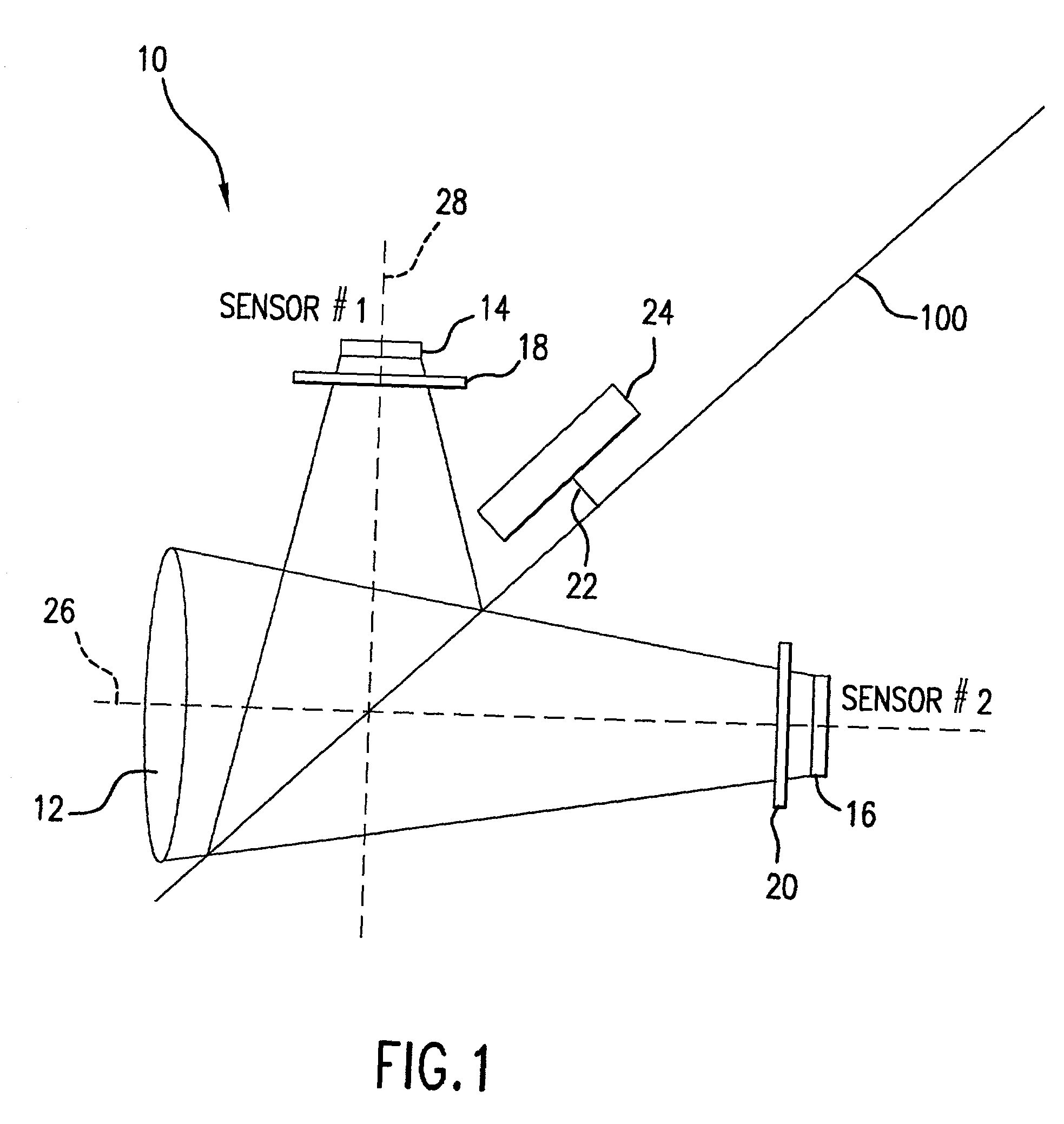
[0053]In FIG. 1, camera 10 includes lens 12, first imaging sensor 14, second imaging sensor 16, and rotatable structure 100. First imaging sensor 14 is disposed to receive light that propagates along reflected axis 28 and second imaging sensor 16 is disposed to receive light that propagates along direct axis 26. Rotatable structure 100 is disposed to define a rotation plane that is oblique to both reflected axis 28 and direct axis 26. In operation, motor 24 rotates axle 22 that in turn rotates rotatable structure 100. Lens 12 focuses an image conjugate onto second imaging sensor 16 along direct axis 26 such that second imaging sensor 16 converts the image light into electrical signals. Lens 12 also focuses the image conjugate onto first imaging sensor 14 along reflected axis 28. The image light through lens 12 along direct axis 26 is reflected from a reflection sector of rotatable structure 100 to propagate along reflected axis 28. First imaging sensor 14 converts the image light in...


PUM


Abstract

A camera includes a first sensor disposed to image light that propagates along a reflected axis, a second sensor disposed to image light that propagates along a direct axis, and a rotatable structure disposed to define a rotation plane that is oblique to both the reflected axis and the direct axis. The rotatable structure includes either a first transmission sector, a first reflection sector disposed adjacent to the first transmission sector, a second transmission sector disposed adjacent to the first reflection sector and a second reflection sector disposed adjacent to the second transmission sector or the rotatable structure includes a first reflection sector, a first opaque sector disposed adjacent to the first reflection sector, and a first transmission sector disposed adjacent to the first opaque sector.

Description

[0001]The priority benefit of the Jan. 24, 2001 filing date of provisional application Ser. No. 60 / 263,528, the Jan. 25, 2001 filing date of provisional application Ser. No. 60 / 263,707, and the Apr. 19, 2001 filing date of provisional application Ser. No. 60 / 284,697 are hereby claimed.BACKGROUND OF THE INVENTION[0002]1. Field of the Invention[0003]The present invention relates to a color cinematography camera with solid state imaging sensors. In particular, the invention relates to a scanning wheel-type color camera using plural sensors.[0004]2. Description of Related Art[0005]Color cameras are known. One type of color camera uses a single CCD imaging sensor with a Bayer pattern overlaying color filter. A Bayer pattern overlaying filter uses four sensor elements per pixel. The overlaying color filter, transmits green light into the first and second sensor elements, transmits blue into the third sensor element and transmits red light into the fourth sensor element. The four elements ...

Claims


Application Information

Patent Timeline
IPC IPC(8): H04N5/225H04N9/09H04N9/097
CPCH04N5/2254H04N9/097H04N5/232H04N23/16
Inventor DYKAAR, DOUGLAS RAYMONDFLOOD, COLIN J.SMITH, CHARLES RUSSELL
Owner TELEDYNE DIGITAL IMAGING INC
Why Eureka
Try Eureka