Camera testing apparatus and method

Inactive Publication Date: 2018-07-26
CORLEY FERRAND D E
View PDF4 Cites 5 Cited by
  • Summary
  • Abstract
  • Description
  • Claims
  • Application Information

AI Technical Summary

Problems solved by technology

This along with variability in the characteristics of the light sources illuminating

Method used


Image

  • Camera testing apparatus and method
  • Camera testing apparatus and method
  • Camera testing apparatus and method

Examples


Embodiment Construction

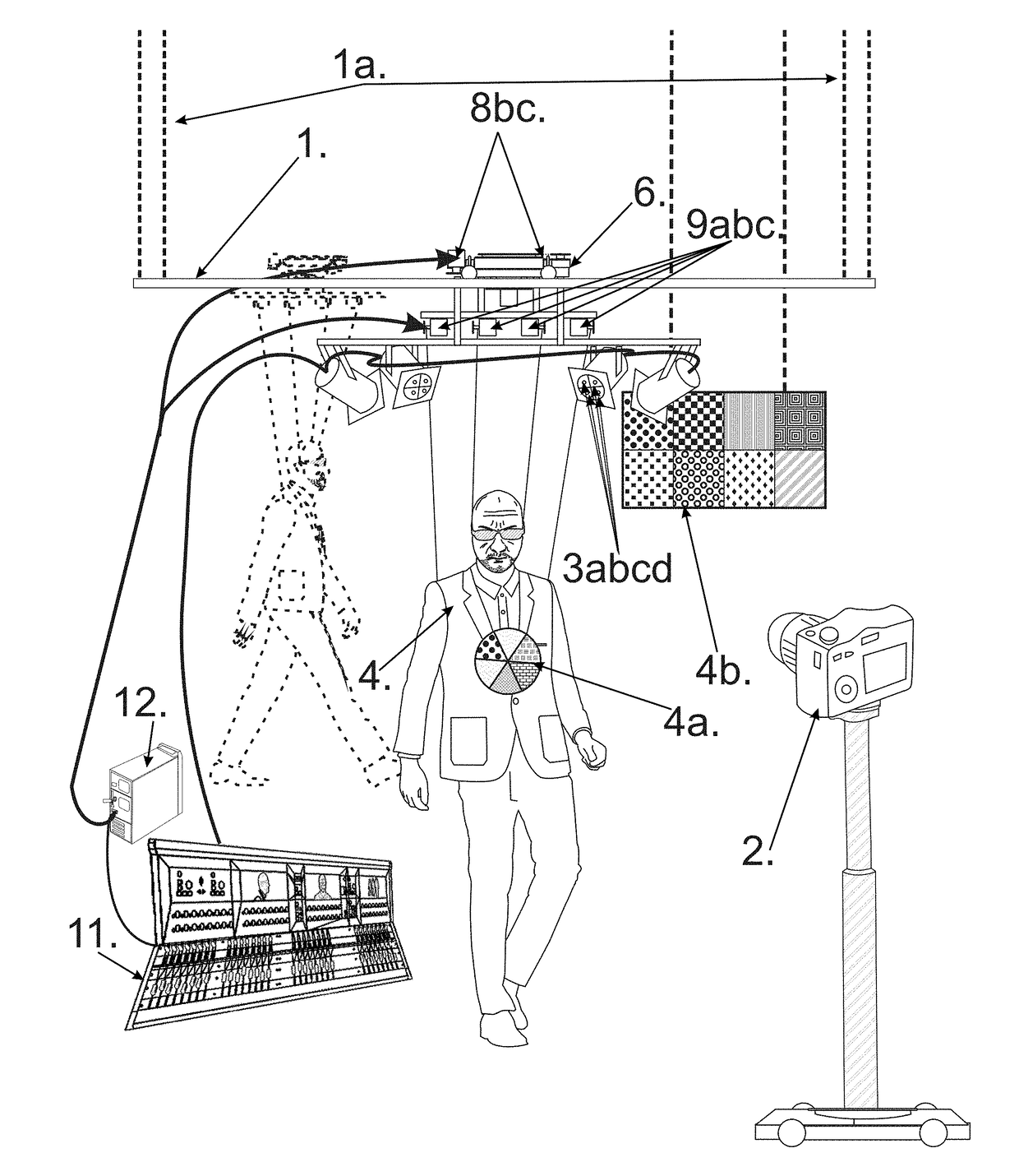
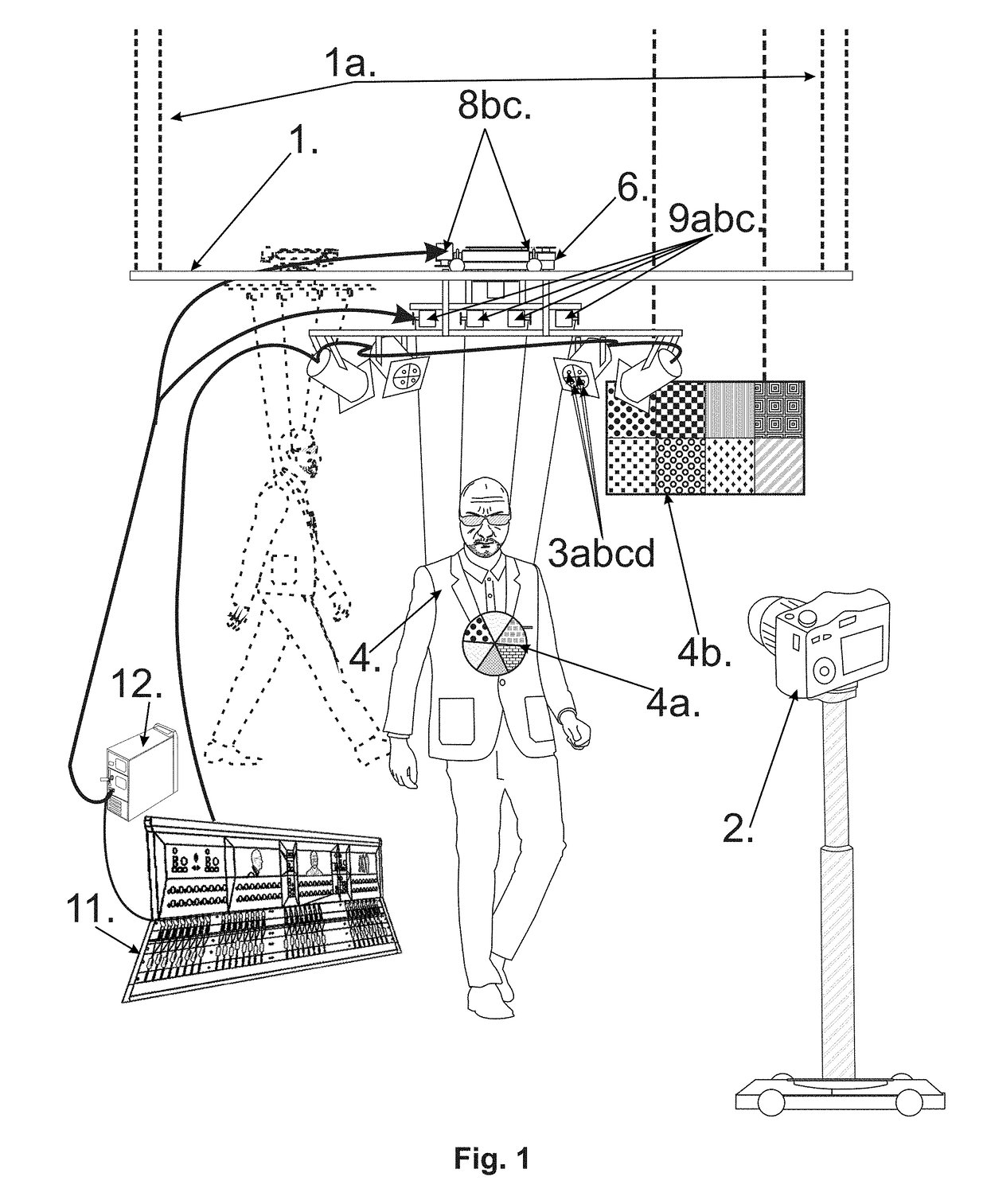
[0021]FIG. 1 shows in this embodiment, main rails (1), which is typically suspended from above on elements (1a). This will provide the camera (2) and lights (3) an unobstructed view of a target object, in this case a human replica (4), hanging from a rotatable member (5).

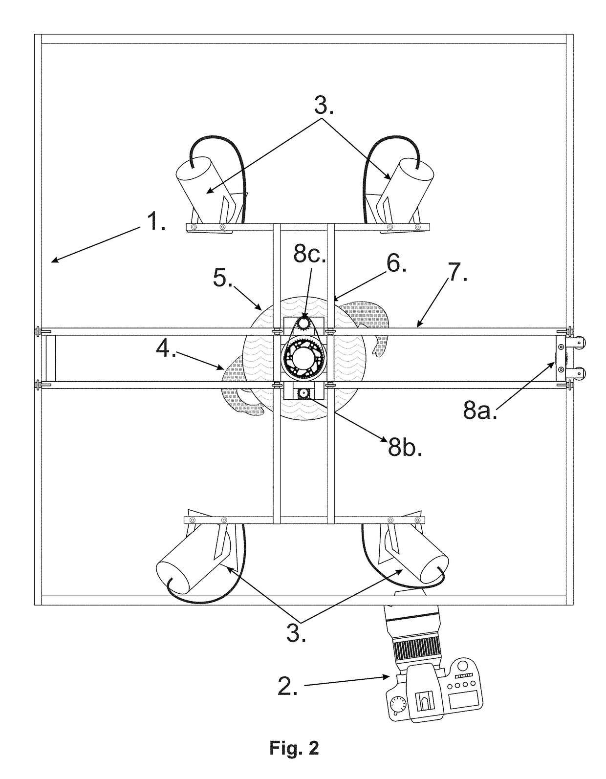
[0022]Member (5) is attached to a cross frame (6) which is supported by beam member (7). Beam (7) is supported at each end on rails (1).

[0023]Three primary motor drives (8a), (8b), and (8c) enable rotatable member (5) and a robotic target, which in this embodiment is shown as a human replica, and / or other test target / s (4a) hanging from the member (5).

[0024]The target will typically have some movable components, such as the arms and legs. However the target may in fact be held stationary and the camera may be moved relative to the target. This may simulate a situation such as the body camera of a police officer, for example. The motor drives (8) are operable so that the target can be moved anywhere within the confin...


PUM


Abstract

The invention is an apparatus designed to solve problems in camera evaluation, namely the selection of camera equipment based on tests that are different to the real world conditions under which the cameras will be used. This is a significant problem, particularly in law enforcement, security and medical imaging. Also disclosed is a method of comparing the performance of two or more movie cameras, under identical simulated real world conditions.

Description

[0001]This application is based on U.S. Provisional application Ser. No. 62 / 448,670 Title: CAMERA TESTING APPARATUS AND METHOD filed Jan. 20, 2017, the priority of which is claimed.FIELD OF THE INVENTION[0002]The invention is designed to solve problems in camera evaluation, namely the selection of camera equipment based on tests under conditions that are different to the conditions under which the cameras will be used. This is a significant problem, particularly in law enforcement, security and medical imaging.[0003]The invetion comprises an apparatus that enables the testing and comparison of moving or still images from multiple cameras, the cameras recording identical two and three dimensional moving reference test targets. Cameras to be tested and compared are placed on a support mechanism that enables one or more cameras to be aligned to the same field of view. Two or more cameras can be tested sequentially or, using beam splitting technology, well known in the trade, simultaneo...

Claims


Application Information

Patent Timeline
IPC IPC(8): H04N17/00H04N17/02H04N5/225
CPCH04N17/002H04N17/02H04N5/2256H04N23/56
Inventor CORLEY, FERRAND D.E.
Owner CORLEY FERRAND D E
Why Eureka
Try Eureka