Utility rack arrangement for a vehicle

a technology for vehicles and racks, applied in the direction of roofs, transportation items, vehicles with loading gates, etc., can solve the problem that certain types of equipment are inherently difficult to transpor

Active Publication Date: 2007-02-20
FCA US
View PDF18 Cites 16 Cited by
  • Summary
  • Abstract
  • Description
  • Claims
  • Application Information

AI Technical Summary

Problems solved by technology

However, certain types of equipment are inherently difficult to transport because of their size, shape, weight, etc.
However,

Method used


Image

  • Utility rack arrangement for a vehicle
  • Utility rack arrangement for a vehicle
  • Utility rack arrangement for a vehicle

Examples


Embodiment Construction

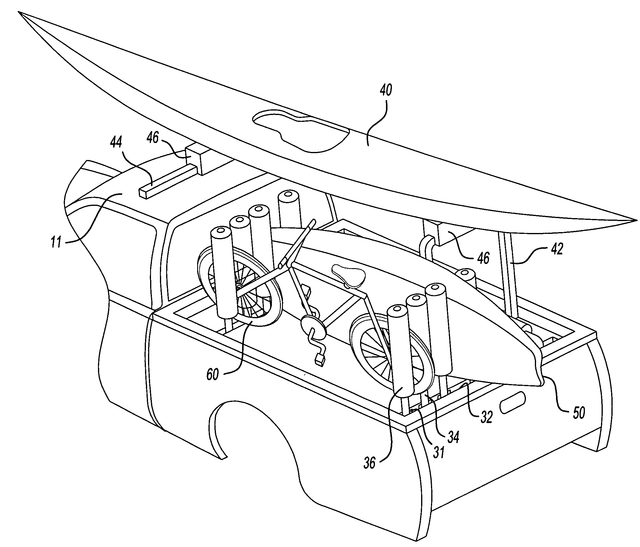
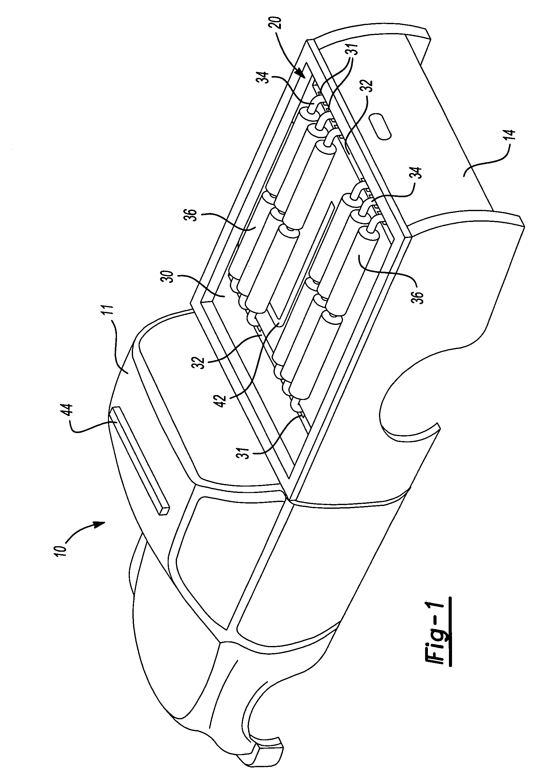
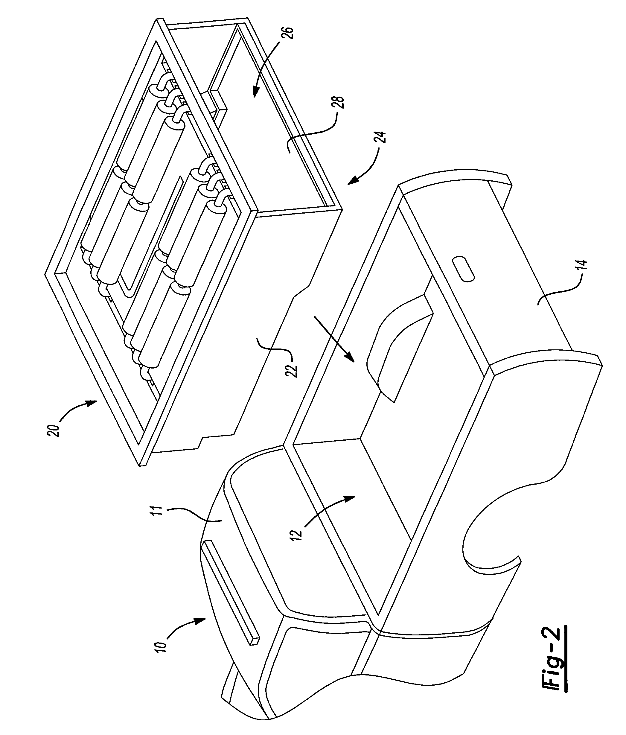
[0017]Referring now to FIG. 1, a vehicle 10, such as a sport utility vehicle, is shown with a utility rack 20 in accordance with the present invention. It should be noted, however, that utility rack 20 could also be installed into a trailer or other vehicles without departing from the spirit and scope of the invention. According to a first exemplary embodiment of the present invention, the utility rack 20 has a platform surface 30, a pair of support rails 32, and a plurality of storage rails 34. The plurality of storage rails 34 are further arranged to pivot between a stowed position, shown, for example, in FIGS. 1 and 3, and a deployed position, shown, for example, in FIGS. 4 and 6. When any of the plurality of storage rails 34 are in the deployed position, they are arranged to receive items between them, such as, for example, a kayak 50, or mountain bike 60.

[0018]The plurality of storage rails 34 are connected to one of the pair of support rails 32 through a slider mechanism 31. T...


PUM


Abstract

A utility rack for a vehicle is provided. The utility rack includes a platform, at least one support rail positioned on the platform, and a plurality of storage rails connected to the at least one support rail. The plurality of storage rails have a stowed position generally parallel to the upper surface, and a deployed position generally perpendicular to the upper surface. The plurality of storage rails are arranged to pivot between the stowed position and the deployed position.

Description

FIELD OF THE INVENTION[0001]The present invention relates generally to a utility rack and storage arrangement for use with a vehicle.BACKGROUND OF THE INVENTION[0002]Pick-up trucks and sport-utility trucks are generally useful for transporting various types of equipment. However, certain types of equipment are inherently difficult to transport because of their size, shape, weight, etc. For this reason, among others, utility racks have been designed to accommodate such equipment. However, these utility racks tend to be suited for only one particular type of cargo and are often permanently fixed to the vehicle.[0003]Thus, there exists a need for an improved utility rack for a vehicle that is easily affixed to the vehicle, easily configurable to carry a varying cargo load, and easily removable.SUMMARY OF THE INVENTION[0004]Accordingly, one aspect of the present invention is to provide a utility rack for a vehicle comprising a platform, at least one support rail positioned on the platfo...

Claims


Application Information

Patent Timeline
IPC IPC(8): B60P3/00
CPCB60P1/003B60R9/00B60P7/135B60P7/08
Inventor MATHER, CARLTEASDALE, TODD RSHAMON, SAMERHUGHES, WILLIAM EGRIFFIN, DANIEL TDAWKINS, DAVID ETHOMAS, RICHMOND P
Owner FCA US
Why Eureka
Try Eureka