Electric junction box

a junction box and electric technology, applied in the direction of electrical apparatus casings/cabinets/drawers, lighting conductor installation, coupling device connection, etc., can solve the problems of constant display, difficult electric junction box layout, poor layout, etc., to reduce the rib-forming space, and drain water efficiently

Inactive Publication Date: 2007-02-20
SUMITOMO WIRING SYST LTD
View PDF9 Cites 30 Cited by
  • Summary
  • Abstract
  • Description
  • Claims
  • Application Information

AI Technical Summary

Benefits of technology

[0008]The present invention has been made in view of the above-described problem. Accordingly, it is an object of the present invention to provide an electric junction box which is capable of complying with a demand for miniaturization thereof and has stable and high watertight performance.

Problems solved by technology

This construction is unfit for the demand for miniaturization of the electric junction box and causes the layout to be bad.
Thus it is difficult for the electric junction box 1 to display constant performance and allow a particular region inside the electric junction box 1 to secure high watertight performance.

Method used


Image

  • Electric junction box
  • Electric junction box
  • Electric junction box

Examples


first embodiment

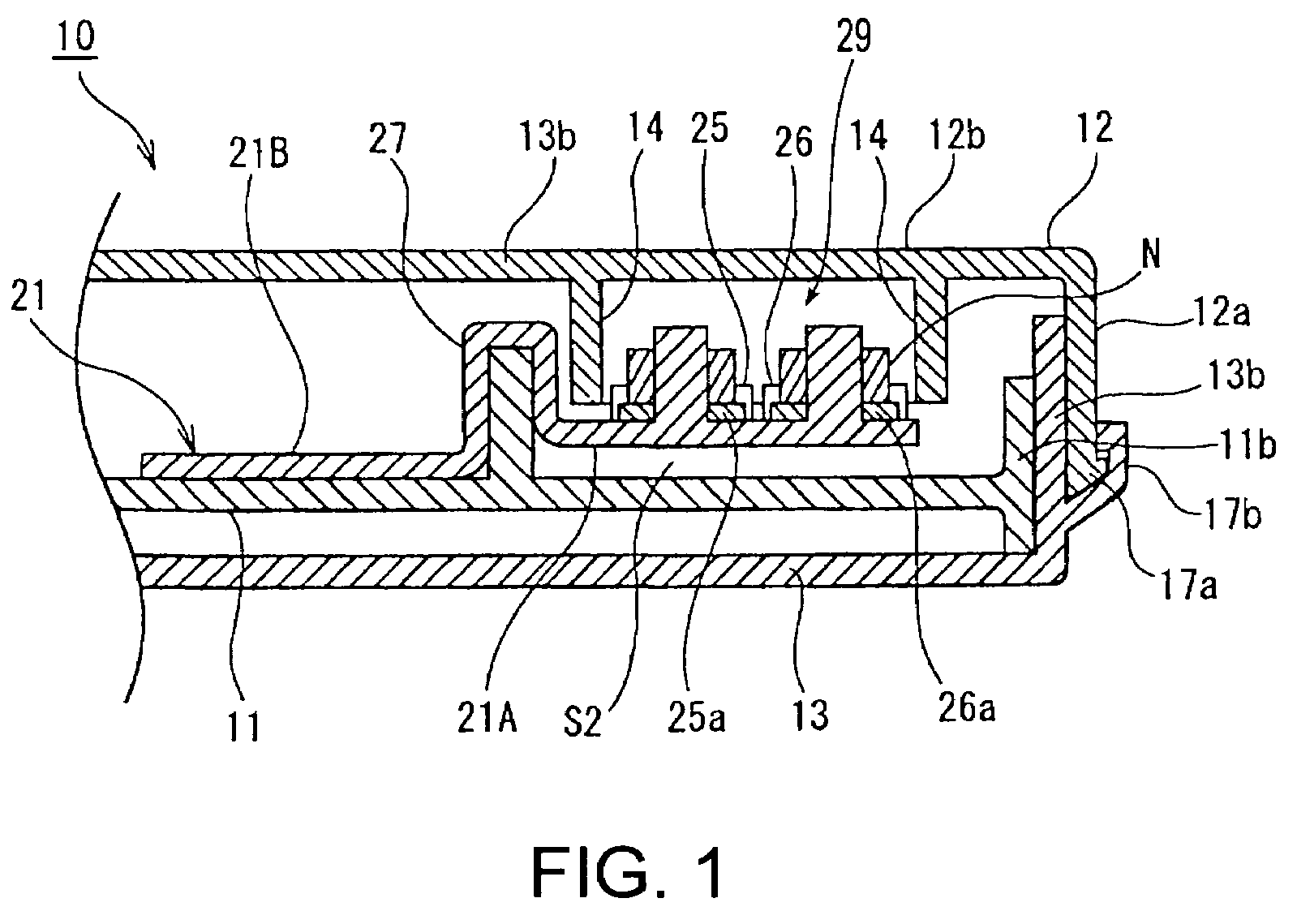
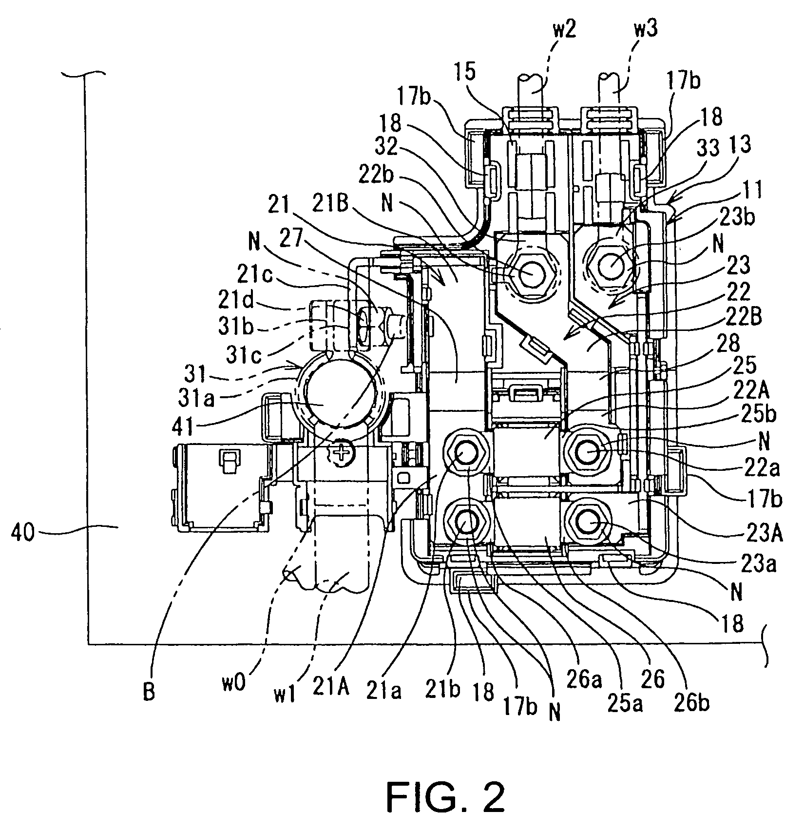
[0035]FIGS. 1 through 7 show an electric junction box 10 of the present invention. The electric junction box 10 has a case body 11; a plurality of bus bars 21, 22, and 23 provided on the case body 11; fusible links 25, 26 connected with the bus bars 21, 22, and 23; and an upper cover 12 and a lower cover 13 mounted on the case body 11 to cover the upper and lower surfaces thereof, with the case body 11, the upper cover 12, and the lower cover 13 connected with one another. The electric junction box 10 is mounted on a battery box 40.

[0036]More specifically, as shown in FIG. 2, one input side bus bar 21 and two output-side bus bar 22, 23 are disposed on an upper surface of the case body 11. An input terminal 25a of the fusible link 25 and an input terminal 26a of the fusible link 26 are fitted on bolts 21a, 21b respectively projected from one side of the input-side bus bar 21 and fastened to the bolts 21a, 21b with nuts N respectively. An output terminal 25b of the fusible link 25 is ...

third embodiment

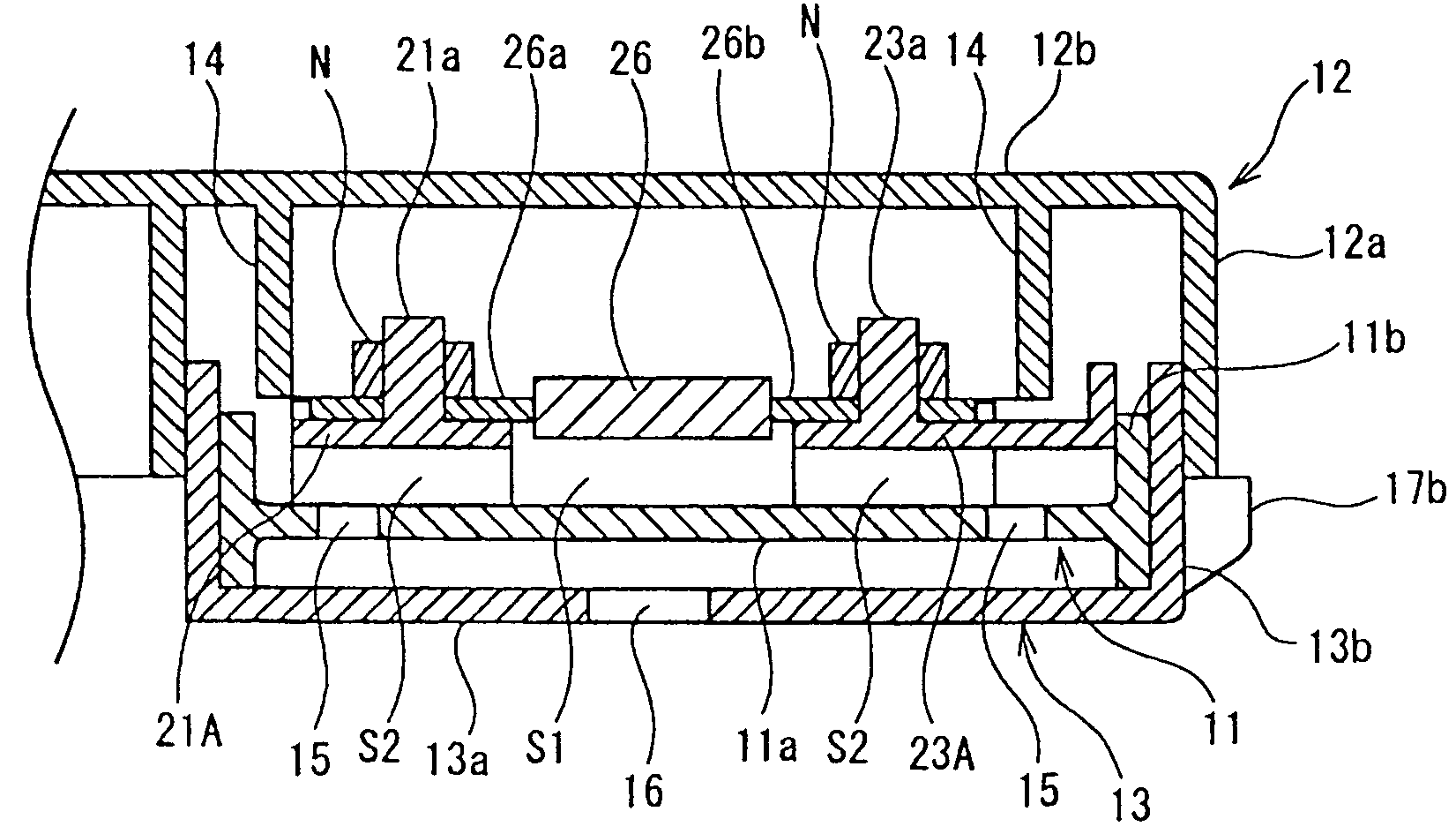
[0056]In the third embodiment, by mounting the upper cover 12 on the case body 11, a peripheral wall 13b of the lower cover 13 is fitted into the gap between the peripheral wall 12a and the rib 14′ both forming the double-wall construction. There by a waterproof wall is formed. Inside the watertight region not surrounded with the rib 14′, the watertight bent portion 27 formed on the inputs ide bus bar 21 and the watertight bent portion 28 formed on the output-side bus bar 23 are disposed. The rib 14 and the watertight bent portions 27, 28 surround the watertight region. In this construction, the rib 14′ and the watertight bent portions 27, 28 surround the four sides of the watertight region, thus waterproofing the watertight region. Further unlike the construction in which a square rib is formed, this construction eliminates the need for forming a space corresponding to one side of a square, thus contributing to miniaturization of the electric junction box.


PUM


Abstract

An electric junction box, disposed in a water penetration region, which accommodates bus bars inside a case body thereof and has fuses (fusible links connected with the bus bars. An upper cover and a lower cover are mounted on the case body 11 with the case body, the upper cover, and the lower cover connected with one another. An entire peripheral wall of the upper cover is formed not as a double-wall construction, but an inner peripheral surface of the peripheral wall is brought into contact with an outer surface of an entire peripheral wall of the lower cover (or case body) to lock the peripheral wall and the entire peripheral wall of the lower cove to each other. In a watertight region including at least the fuses, a rib is projected in the shape of a frame from an inner surface of an upper wall of the upper cover so that the rib surrounds the watertight region.

Description

BACKGROUND[0001]1. Field of the Invention[0002]The present invention relates to an electric junction box. More particularly the present invention is intended to make the electric junction box compact by improving a watertight construction thereof.[0003]2. Description of the Related Art[0004]As the conventional watertight construction of the electric junction box mounted on vehicles and the like, the construction shown in Japanese Patent Application Laid-Open No. 9-308053 (patent document 1) is known. More specifically, as shown in[0005]FIG. 12, the electric junction box 1 includes a case body 2 in which the bus bar 6 and the fuse 7 are mounted, the upper cover 3 mounted on the upper surface of the case body 2 to cover the upper surface thereof, and a lower cover 4 mounted on the lower surface of the case body 2 to cover the lower surface thereof. The case body 2 and the upper cover 3 are locked to each other with a locking portion 5a. The case body 2 and the lower cover 4 are locked...

Claims


Application Information

Patent Timeline
Patent Type & Authority Patents(United States)
IPC IPC(8): H02G3/08
CPCH02G3/088
Inventor KANAZAWA, MASASHI
Owner SUMITOMO WIRING SYST LTD
Why Eureka
Try Eureka