Receptacle for enclosing low-voltage electronic devices in a wall

a technology for electronic devices and enclosures, applied in the direction of gaseous cathodes, electrical apparatus casings/cabinets/drawers, coupling device connections, etc., can solve the problems of building materials degrading, building moisture condense inside the walls and ceilings of the building, and increasing the cost of heating the structur

Inactive Publication Date: 2007-03-06
PROFESSIONAL PARTNERS
View PDF40 Cites 13 Cited by
  • Summary
  • Abstract
  • Description
  • Claims
  • Application Information

AI Technical Summary

Problems solved by technology

If warm air from inside the building penetrates the vapor barrier, moisture from this air may condense inside the walls and ceilings of the building.
This condensed moisture can promote mold growth and cause building materials to degrade.
The loss of warm air from the inside of the building to the outside of the building also increases the cost of heating the structure.
Even when an installer is highly skilled, this task is very time consuming.

Method used


Image

  • Receptacle for enclosing low-voltage electronic devices in a wall
  • Receptacle for enclosing low-voltage electronic devices in a wall
  • Receptacle for enclosing low-voltage electronic devices in a wall

Examples


Embodiment Construction

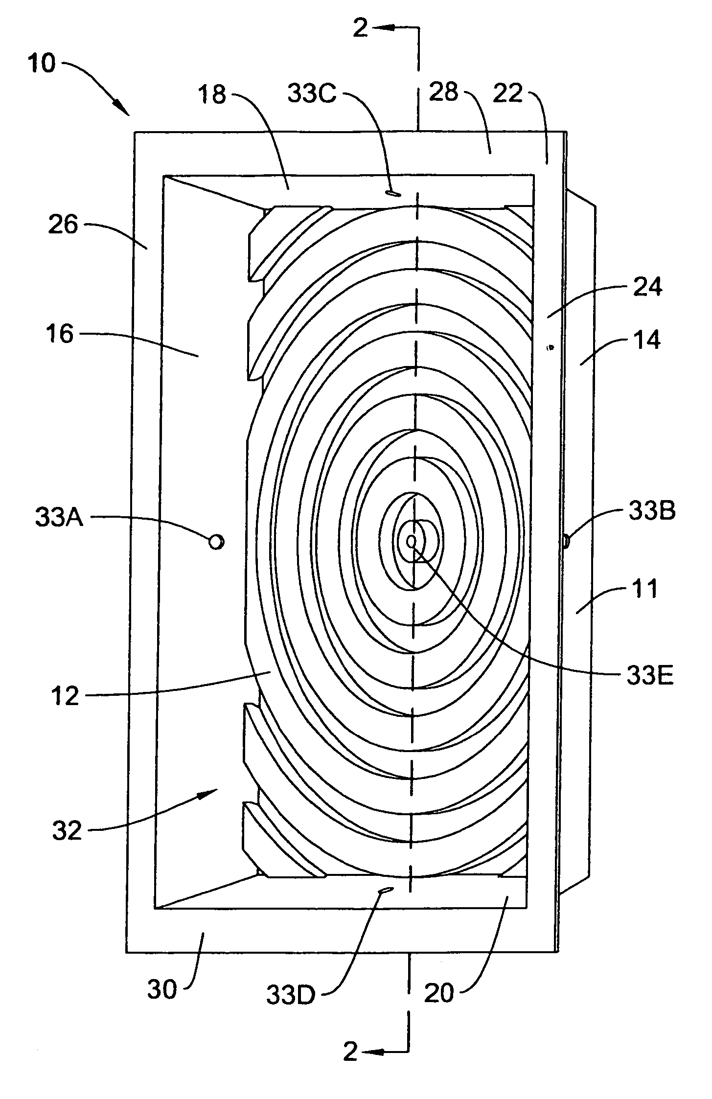
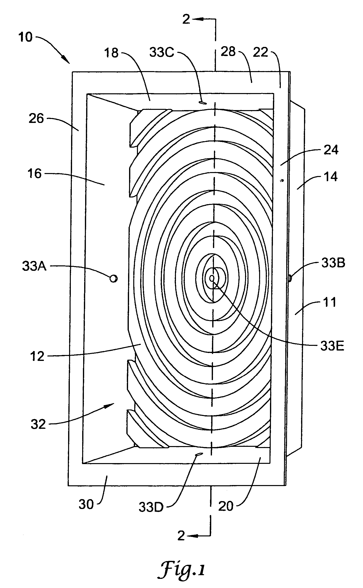
[0016]Reference is now made to the figures, in which like element numbers refer to like elements throughout. FIG. 1 is a perspective view of a receptacle shown generally by element number 10. Receptacle 10 includes a base 12, and four side walls 14, 16, 18, and 20. Each side wall is joined to two adjacent side walls to form a perimeter wall 11. Perimeter wall 11 is joined to base 12 and extends from base 12 in a generally perpendicular fashion. Perimeter wall 11 and base 12 delineate a generally rectangular enclosure with five closed sides and one open side.

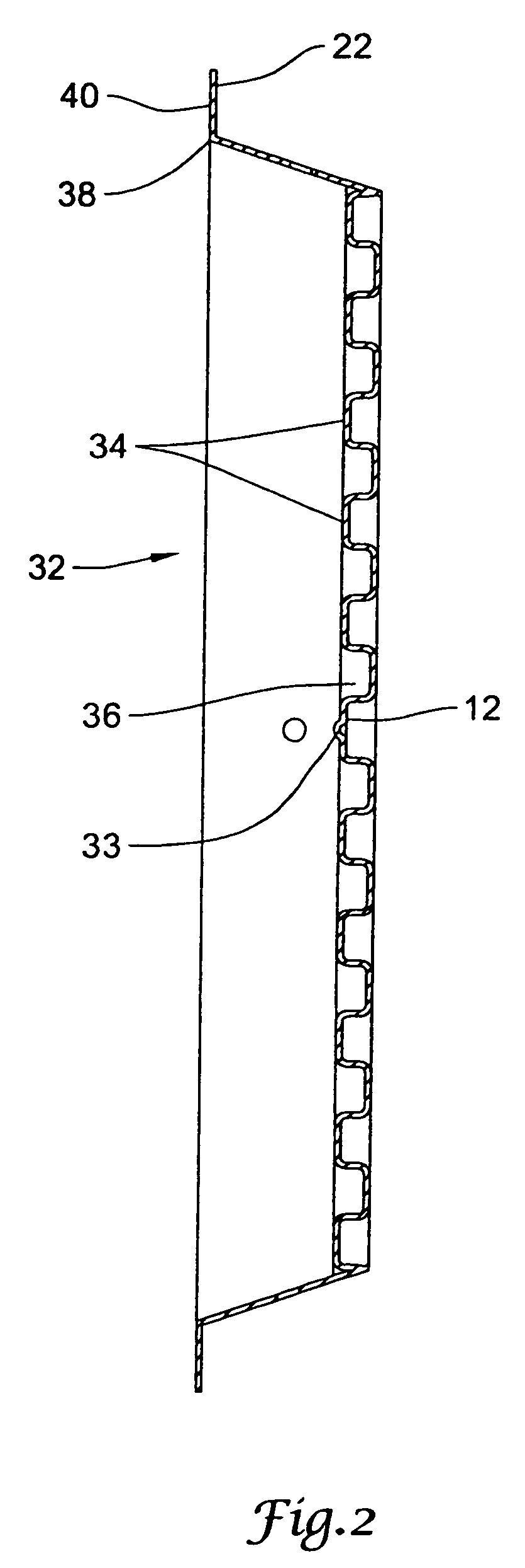
[0017]A mounting flange 22 is joined to side walls 14, 16, 18, and 20. Mounting flange 22 is comprised of side flanges 24 and 26, top flange 28 and bottom flange 30. Flanges 24, 26, 28, and 30 extend in a generally perpendicular fashion from side walls 14, 16, 18, and 20 respectively.

[0018]Base 12 includes a pattern of concentric geometrical shapes shown generally at 32. As shown in FIG. 1, the center of pattern 32 is generally a...


PUM


Abstract

A receptacle for enclosing low-voltage electronic devices and maintaining the integrity of a vapor barrier. The receptacle forms a cavity having an open side. The receptacle may be mounted within a wall having a vapor barrier and an outer layer. The vapor barrier may be sealed to the receptacle and the outer layer and the vapor barrier may extend over the receptacle to enclose the space within the cavity, thereby forming an airtight enclosure.

Description

[0001]This application is continuation application of U.S. patent application Ser. No. 10 / 677,020 filed Oct. 1, 2003, which is a continuation application of U.S. patent application Ser. No. 09 / 516,199 filed Feb. 29, 2000, now U.S. Pat. No. 6,660,936, which is a continuation application of U.S. patent application Ser. No. 09 / 193,876 filed on Nov. 18, 1998, now U.S. Pat. No. 6,031,181.FIELD OF THE INVENTION[0002]The present invention relates generally to components for building construction. More particularly, the present invention relates to receptacles for enclosing low voltage electronic devices.BACKGROUND OF THE INVENTION[0003]With the rising cost of energy, efforts have been made to provide homes and other buildings with insulation which will more efficiently prevent the loss of heat to the outside. Modem building techniques include the installation of a vapor barrier in the walls of homes or other buildings.[0004]The vapor barrier contains warm, moist air inside the building. If...

Claims


Application Information

Patent Timeline
Patent Type & Authority Patents(United States)
IPC IPC(8): H01H9/02H02G3/08H02G3/12
CPCH02G3/088H02G3/121H02G3/12
Inventor JACKS, CRAIG A.
Owner PROFESSIONAL PARTNERS
Why Eureka
Try Eureka