
Edge reinforced brittle armor system

a technology of brittle armor and reinforcement, applied in the direction of armor, protective equipment, weapons, etc., can solve the problems of inability to modify or complete existing or built structures, the outermost peripheries and edges of brittle armor panels, and the inability to meet the needs of use, so as to reduce or ameliorate the effect of vulnerability

Inactive Publication Date: 2007-03-20
UNITED STATES OF AMERICA THE AS REPRESENTED BY THE SEC OF THE ARMY
View PDF10 Cites 38 Cited by
  • Summary
  • Abstract
  • Description
  • Claims
  • Application Information

AI Technical Summary

Benefits of technology

[0002]This invention generally pertains to a reinforcement for brittle armor panels, and more especially for transparent armor plates, to thereby reduce or ameliorate vulnerability by attacks with threat projectiles launched at their outermost perimeters and/or edges. Security

Problems solved by technology

Security structures or vehicles using these armors are potential targets of terrorists, assailants, and hostile forces that employ a plurality of firearms; explosive devices, shell fragments, and like high velocity projectiles to attack brittle armors on or within security structures.
Through extensive research with high velocity projectiles, I have observed that the outermost peripheries and edges of brittle armor panels, regardless of their major materials of construction, are less durable and efficient than their central areas.
Yet, this modification may not be practical for already completed or built structures, and it is very possible that occupant fields of view could be impaired.
From the standpoint of safety and security, any obscured vision for occupants of a security structure is undesirable, and it could result in regrettable outcomes.
Moreover, this approach can undesirably increase structure or vehicle weight.
However, these approaches might result in highly questionable modifications, increased expenses, and unsuitable structural effects for very small gains in overall armor performance.
Additionally, this latter approach will definitely increase the thickness and weight of a considerably bulky component that is already cumbersome to work with for most applications.

Method used


Image

  • Edge reinforced brittle armor system
  • Edge reinforced brittle armor system
  • Edge reinforced brittle armor system

Examples


Embodiment Construction

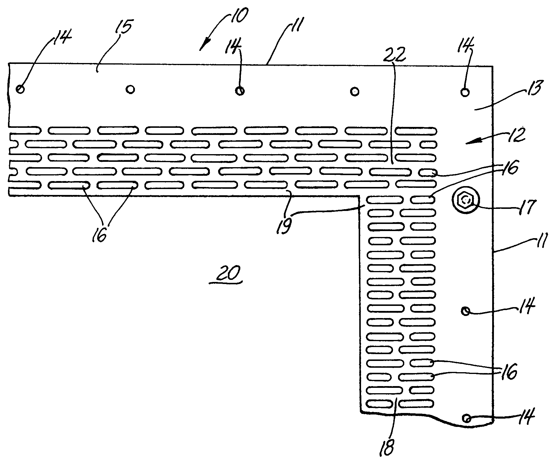
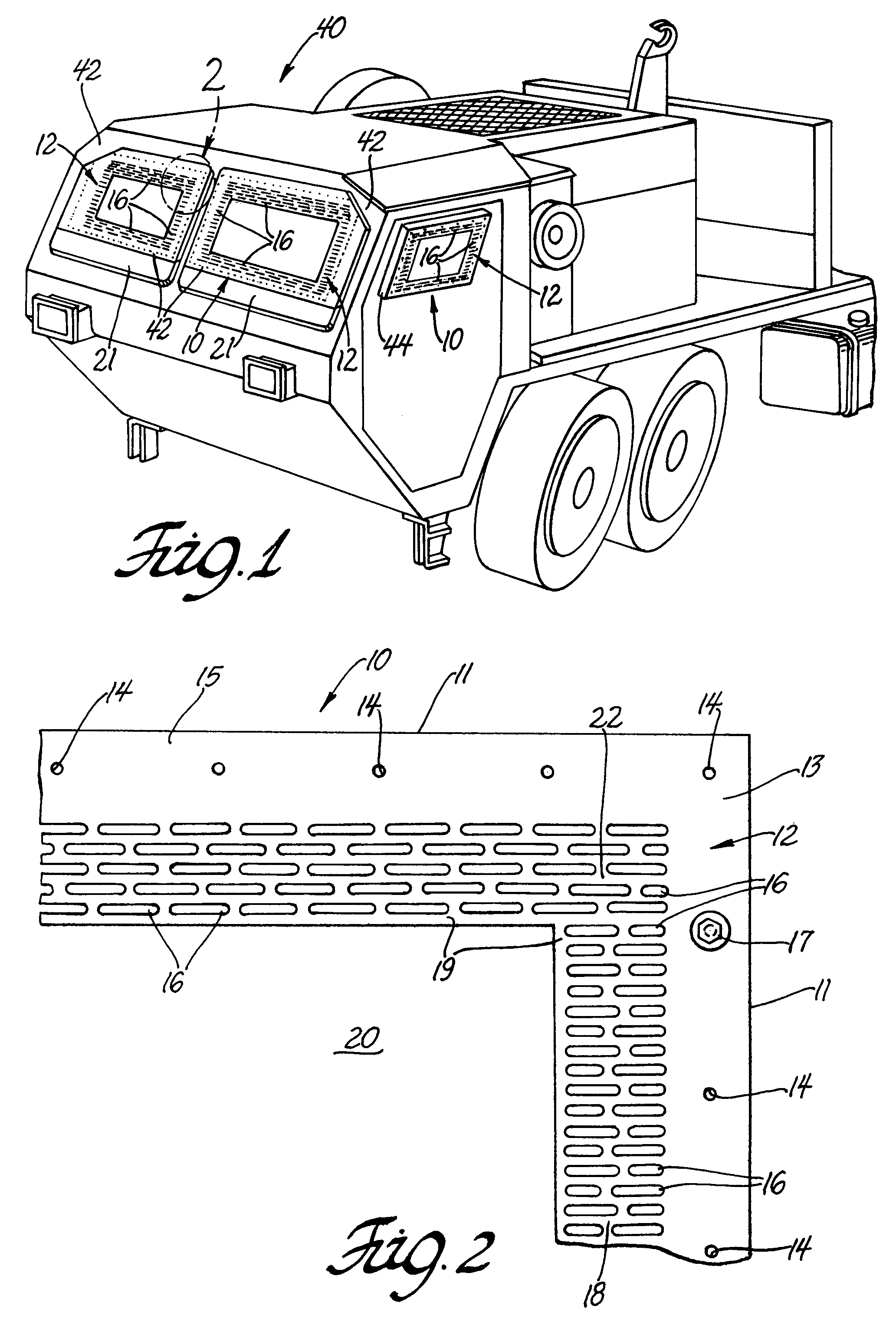
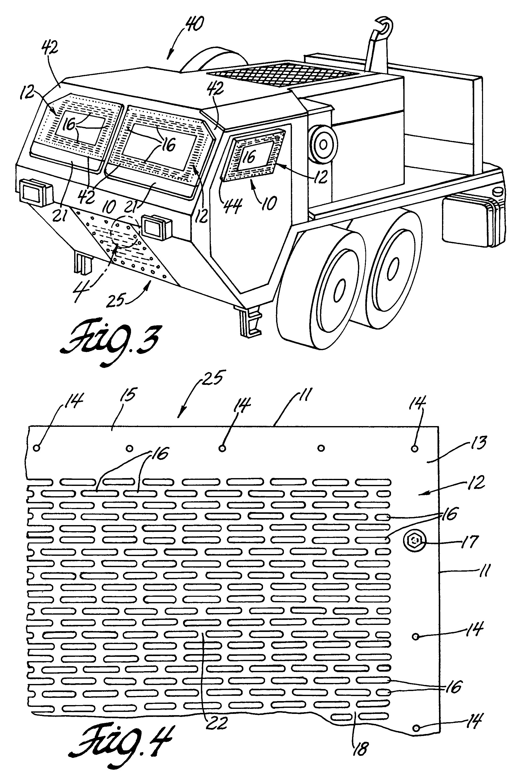
[0021]According to my invention, and referring to FIG. 2, there is shown therein my centrally apertured shield 10 which is used for reinforcement of the extreme, outer edges of a transparent armor plate of a windowed security structure. This shield is substantially a parallelogram in form that comprises two upright members 13 that intercept a pair of cross members 15 to thereby define an internal, central aperture 20. Although a rectangular aperture is depicted in FIG. 2, it should be understood that round, elliptical, oblong, oval, square, and other shapes are feasible as this aperture.

[0022]Positioned in a perforation field 22 immediately adjacent to said central aperture, but remote from the shield's outermost edges 11, are a multiplicity of overlapping slots or perforations 16, occurring in a predetermined size, shape, and amount. It is expected that this perforation pattern could be identical for both the cross 15 and upright 13 members. Alternatively, the pattern for the uprig...


PUM


Abstract

An edge reinforcement for brittle armor plates is described and claimed herein for improving the ballistic performance of the outer peripheral margins of such plates to incoming threat projectiles. Typically, a transparent armor is positioned within a windowed opening of a security structure. Examples of contemplated security structures protected by my shields are civilian light-armored vehicles, military tactical trucks, and combat vehicles. My reinforced armor system deploys a shield of a hardened material, over and outboard of a brittle armor. Typically, this shield is positioned parallel planar to the brittle armor. If desired, my shield may extend slightly beyond the armor plate and mounting apparatuses. Fortuitously, the reinforced brittle armor plate has more strength than that of the central portion, or even exceeds it. Thereby, said plate will not be defeated merely because threat projectiles impact its weaker margins.

Description

GOVERNMENT INTEREST[0001]The invention described herein may be made, used, and licensed by, or for, the United States Government for governmental purposes without paying me any royalty.BACKGROUND AND SUMMARY[0002]This invention generally pertains to a reinforcement for brittle armor panels, and more especially for transparent armor plates, to thereby reduce or ameliorate vulnerability by attacks with threat projectiles launched at their outermost perimeters and / or edges. Security structures or vehicles using these armors are potential targets of terrorists, assailants, and hostile forces that employ a plurality of firearms; explosive devices, shell fragments, and like high velocity projectiles to attack brittle armors on or within security structures.[0003]Herein, I provide a choice of opaque armor panels and shields to reinforce brittle armor systems by outboard deployment of the shield over an external face of an exposed, brittle armor panel. For transparent armor plates, my prefe...

Claims


Application Information

Patent Timeline
IPC IPC(8): F41H5/02
CPCF41H5/013F41H5/263F41H5/0407F41H5/023
Inventor GONZALEZ, RENE' G.
Owner UNITED STATES OF AMERICA THE AS REPRESENTED BY THE SEC OF THE ARMY
Learn More