
System and method for interactively rendering objects with surface light fields and view-dependent opacity

a technology of surface light field and view-dependent opacity, applied in the field of rendering threedimensional objects, can solve the problems of reducing rendering performance, unable to render such objects from parametric or geometric models such as polygon meshes, and limited surface light field approaches due to the complexity of the object's geometry

Inactive Publication Date: 2007-03-20
MITSUBISHI ELECTRIC RES LAB INC
View PDF6 Cites 14 Cited by
  • Summary
  • Abstract
  • Description
  • Claims
  • Application Information

AI Technical Summary

Benefits of technology

[0010]The invention provides a hardware-accelerated system and method for rendering surface light fields with an opacity hull. The method enables interactive visualization of objects that have complex reflectance properties, and elaborate geometrical, texture, and color details. The opacity hull is a three dimensional shape enclosing the object with view-dependent opacity values parameterized onto that shape.

Problems solved by technology

Because of their intricate shapes, and complex lighting properties, it is practically impossible to render such objects from parametric or geometric models such as polygon meshes.
Surface light field approaches are limited by the complexity of the object's geometry.
A dense mesh requires many vertices and leads to a decrease in rendering performance.
Faster rendering with a coarse mesh leads to artifacts that are most noticeable at the silhouette of the object.
However, clipping is impractical for complex silhouette geometry such as trees, feathers, and furry textures.
However, point models for opacity light fields are impracticably large, requiring on the order of 2–4 Gigabytes of memory, and it is difficult to accelerate point-based rendering method with graphics hardware.
Consequently, it can take up to thirty seconds to render a frame, clearly not interactive.

Method used


Image

  • System and method for interactively rendering objects with surface light fields and view-dependent opacity
  • System and method for interactively rendering objects with surface light fields and view-dependent opacity
  • System and method for interactively rendering objects with surface light fields and view-dependent opacity

Examples


Embodiment Construction

System and Method Overview

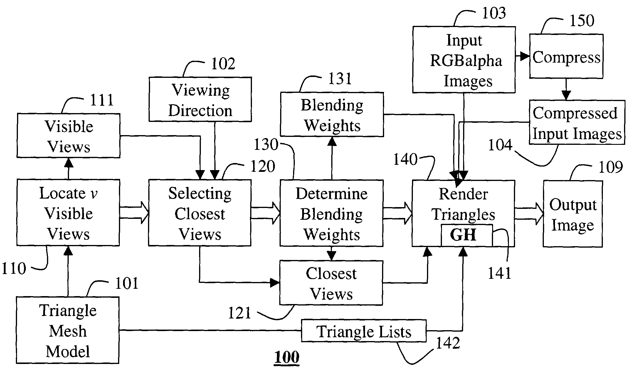
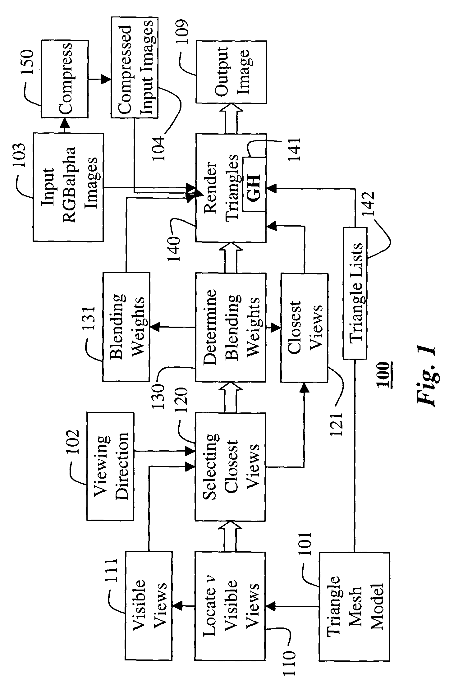
[0022]FIG. 1 shows a system and method 100 according to the invention. The system and method 100 interactively render surface light fields with view-dependent opacity light fields. The rendering can generate an output image 109 from a model of a complex textured object for arbitrary viewing directions.

[0023]The input to the system 100 includes a triangular mesh 101, a viewing direction 102, and an input set of rectified RGBα images 103. The mesh 101 defines a surface shape or model of the object. Any known method for generating a polygon mesh model for an object can be used. The direction d 102 indicates a point of view for the output image 109, The input images 103 are acquired of the object by cameras at a fixed number of camera locations. The images can be digitized color photographs, or images acquired with a digital camera.

[0024]The method 100 includes the following steps. For each vertex v in the mesh 101, locate 110 a set of visible views 111. A vert...


PUM


Abstract

A method renders a model of a 3D object. A polygon model of the 3D object is generated, and a set of input images are acquired of the object. For each vertex of the polygon model, a set of visible views are located, and a set of closest views are selected from the visibility views. Blending weights are determined for each closest view. Then, the each polygon in the model is rendered into an output image. The rendering is performed by blending images of the set of input images corresponding to the set of closest views of each vertex of the polygon using the blending weights.

Description

FIELD OF THE INVENTION[0001]This invention relates generally to rendering three-dimensional objects, and more particularly to rendering arbitrary views of objects from a limited set of photographs acquired of the objects.BACKGROUND OF THE INVENTION[0002]Often, it desired to interactively render 3D objects that have complex reflectance properties and elaborate surface details. Good examples are trees, grass, furry Teddy bears, feathers, and filled wineglasses. Because of their intricate shapes, and complex lighting properties, it is practically impossible to render such objects from parametric or geometric models such as polygon meshes. Therefore, models for these types of objects are usually constructed and rendered from high-resolution images acquired of the objects. This technique is generally known as image-based rendering.[0003]Early image-based rendering methods required a very large set of images to achieve high rendering quality, see McMillan et al., “Plenoptic modeling: An i...

Claims


Application Information

Patent Timeline
Patent Type & Authority Patents(United States)
IPC IPC(8): G06K9/00G06T17/00G06T15/20
CPCG06T15/205
Inventor VLASIC, DANIELPFISTER, HANSPETERMATUSIK, WOJCIECH
Owner MITSUBISHI ELECTRIC RES LAB INC
Learn More