Latch bolt

a technology of latch bolts and latch mechanisms, which is applied in the direction of carpet fasteners, wing accessories, and applications for locking, etc., can solve the problems of limited use, difficult to absorb large impacts, and unsatisfactory in certain applications

Inactive Publication Date: 2007-03-27
MERITOR TECH
View PDF16 Cites 28 Cited by
  • Summary
  • Abstract
  • Description
  • Claims
  • Application Information

AI Technical Summary

Benefits of technology

[0008]The present invention provides a latch mechanism suitable for a vehicle including a chassis and a latch bolt. The latch bolt is movably mounted on the chassis, and the chassis includes an abutment for an over-travel buffer. The latch bolt is moveable between an open position in which the latch bolt can receive a striker of a vehicle, a closed position in which the striker is capable of being retained by the latch bolt, and an over-travel position. The latch mechanism includes an over-travel buffer which has a displacing element and an engagement portion. The over-travel buffer operably acts between the abutment of the chassis and the latch bolt to absorb over-travel of the latch bolt. The displacing element is moveable frictionally against the engagement portion during over-travel and generates frictional force to absorb over-travel energy of the latch bolt.

Problems solved by technology

These single cavity based buffers have difficulty absorbing large impacts and therefore only have limited use as over-travel buffers.
Consequently, they are not ideal in certain applications.

Method used


Image

  • Latch bolt
  • Latch bolt
  • Latch bolt

Examples


Embodiment Construction

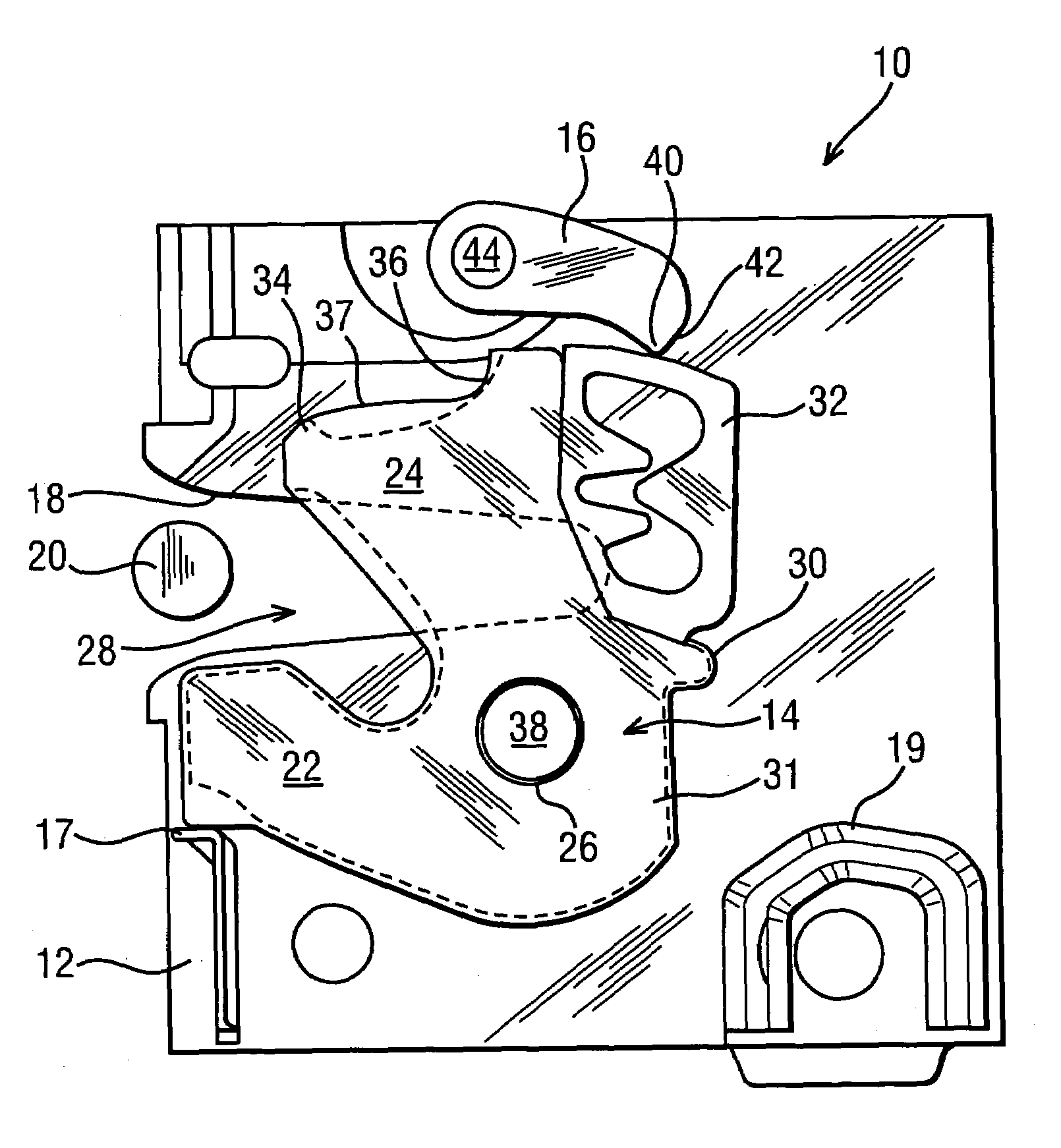
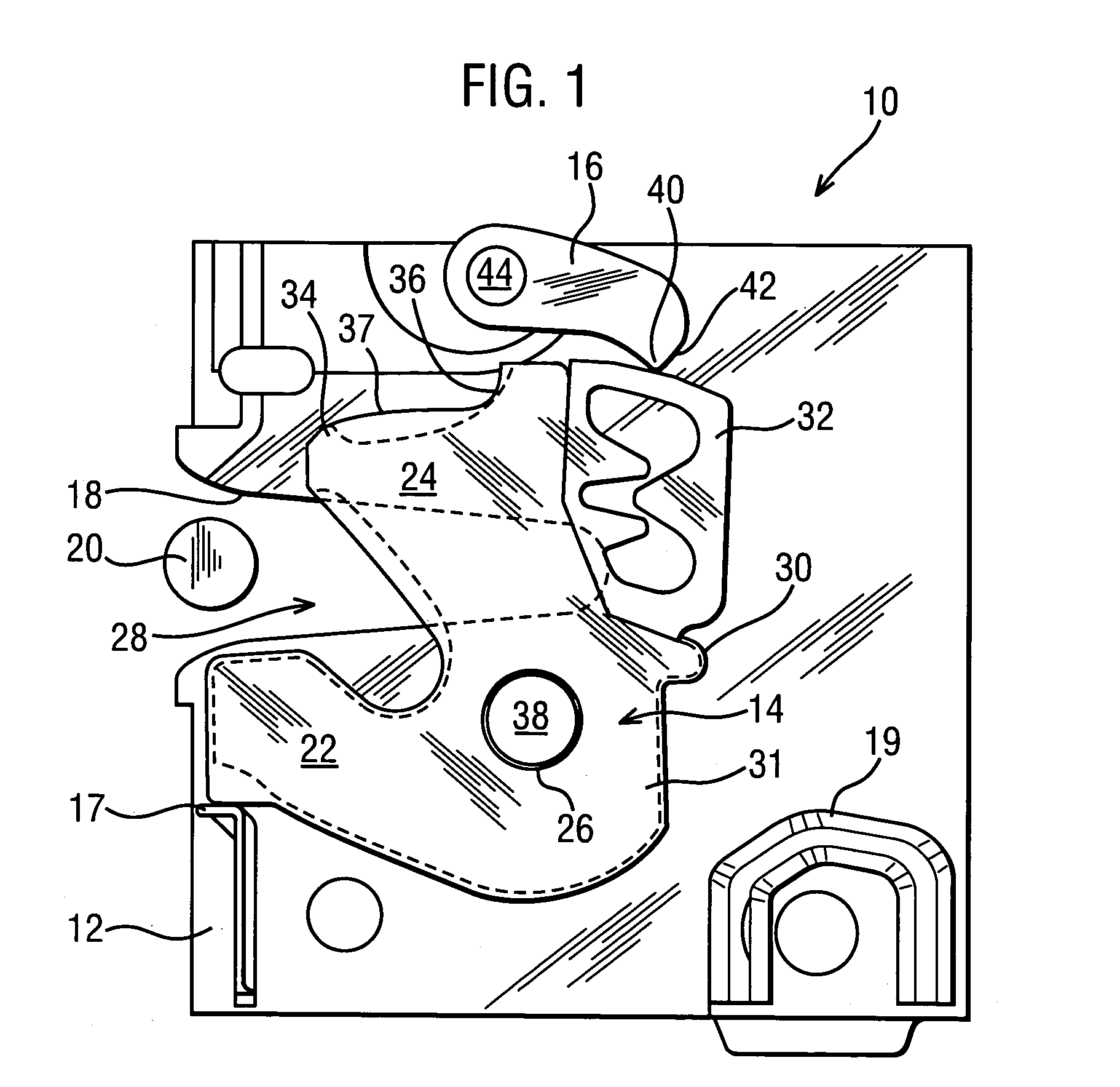
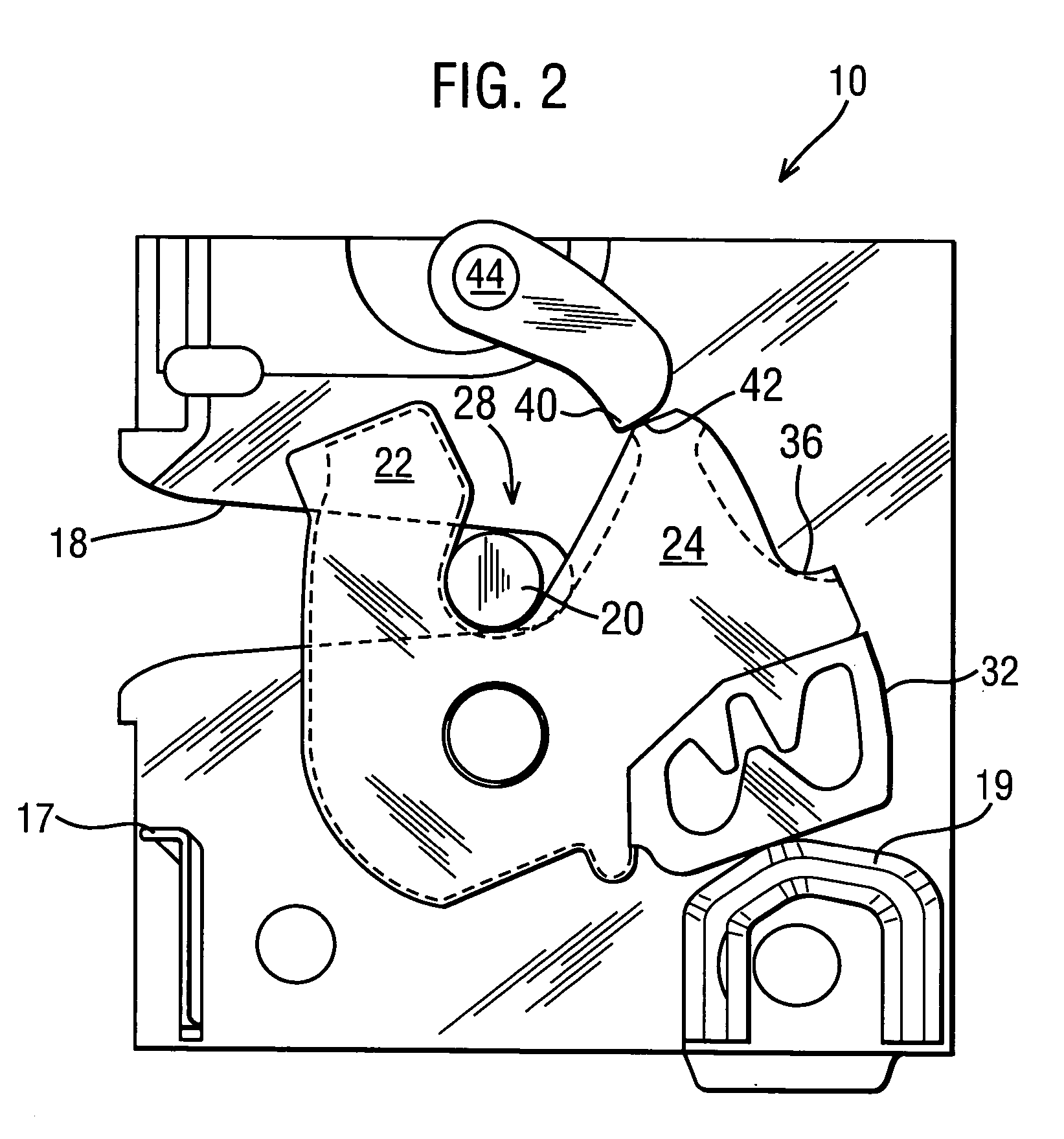
[0019]Referring to FIGS. 1 to 3, a latch mechanism 10 includes a chassis 12 having a latch bolt 14, in the form of a rotating claw, and a pawl 16 mounted on the chassis 12.

[0020]The chassis 12 includes a retention plate having a lateral slot (or striker mouth) 18 that is capable of permitting entry of a striker 20. The chassis 12 also includes an open latch abutment 17 and an over-travel abutment 19. The over-travel abutment 19 may include an elastomeric material that can absorb some energy of an impact.

[0021]However, in further embodiments, the over-travel abutment 19 can be rigid, thus requiring an over-travel buffer 32 (see below) to provide all of the over-travel buffering requirements.

[0022]The latch bolt 14 includes a shaped metal substrate (not shown) having a central hole 26 and two arms 22 and 24 that define a recess 28. An overmold 30 of an elastomeric material surrounds the metal substrate. The overmold 30 includes a main body 31 and the over-travel buffer 32. The arm 24 ...


PUM


Abstract

A latch mechanism includes a chassis and a latch bolt movably mounted on the chassis. The chassis includes an abutment, and the latch bolt is moveable between an open position in which the latch bolt can receive a striker of a vehicle, a closed position at which the striker is capable of being retained by the latch bolt, and an over-travel position. The latch mechanism includes a buffer having a displacing element and an engagement portion. The buffer is capable of operably acting between the abutment and the latch bolt to absorb over-travel of the latch bolt. The displacing element is capable of moving frictionally against the engagement portion during over-travel to generate a frictional force to absorb over-travel energy of the latch bolt.

Description

REFERENCE TO RELATED APPLICATIONS[0001]This application claims priority to Great Britain patent application GB 0321909.4 filed on Sep. 19, 2003.TECHNICAL FIELD[0002]This invention relates generally to latch mechanisms and latch bolts for latch mechanisms that are primarily intended for use on a closure of a motor vehicle.BACKGROUND OF THE INVENTION[0003]A latch bolt for a car door includes one or more energy-absorbing buffers to lower noise during operation of the latch mechanism of the latch bolt. The energy-absorbing buffers can be located in a variety of positions on the latch bolt, depending on what type of impact the energy-absorbing buffers are intended to absorb energy from. Energy-absorbing buffers are commonly located to absorb some of the impact between the latch bolt and an open latch abutment as the latch bolt moves, under spring bias, from a closed position to an open position. At the closed position, a striker mounted on the door frame is retained by the latch bolt. Wh...

Claims


Application Information

Patent Timeline
Patent Type & Authority Patents(United States)
IPC IPC(8): E05C3/16E05B65/32E05B17/00E05C3/06E05C17/64
CPCE05B85/26E05B77/40E05B77/38Y10S292/23Y10S292/56Y10T292/1047Y10T292/1082
Inventor KETELSEN, MORTENGORTON, JOHN
Owner MERITOR TECH
Why Eureka
Try Eureka