
Systems and methods for testing conductive members employing electromagnetic back scattering

a technology of electromagnetic back scattering and conductive members, applied in the direction of resistance/reactance/impedence, flaw detection using microwaves, instruments, etc., can solve the problems of degrading the structural integrity of the pipeline system, and visual inspection is also impossible withou

Inactive Publication Date: 2007-03-27
EMGWIP LLC
View PDF106 Cites 20 Cited by
  • Summary
  • Abstract
  • Description
  • Claims
  • Application Information

AI Technical Summary

Benefits of technology

Enables the detection of anomalies along extended lengths of insulated and shielded pipes, determining the presence, extent, and location of corrosion by analyzing impedance changes caused by reflections from the electromagnetic pulses, improving the assessment of pipeline integrity without physical intervention.

Problems solved by technology

Corrosion of steel pipes can degrade the structural integrity of the pipeline system.
For insulated, shielded pipes, visual inspection is impossible without physically removing the insulation and outer shield.
For buried pipes, visual inspection is also impossible without excavating the pipe.
However, acoustic wave propagation and x-ray radiography are only applicable to a single point location or over a short distance.

Method used


Image

  • Systems and methods for testing conductive members employing electromagnetic back scattering
  • Systems and methods for testing conductive members employing electromagnetic back scattering
  • Systems and methods for testing conductive members employing electromagnetic back scattering

Examples


Embodiment Construction

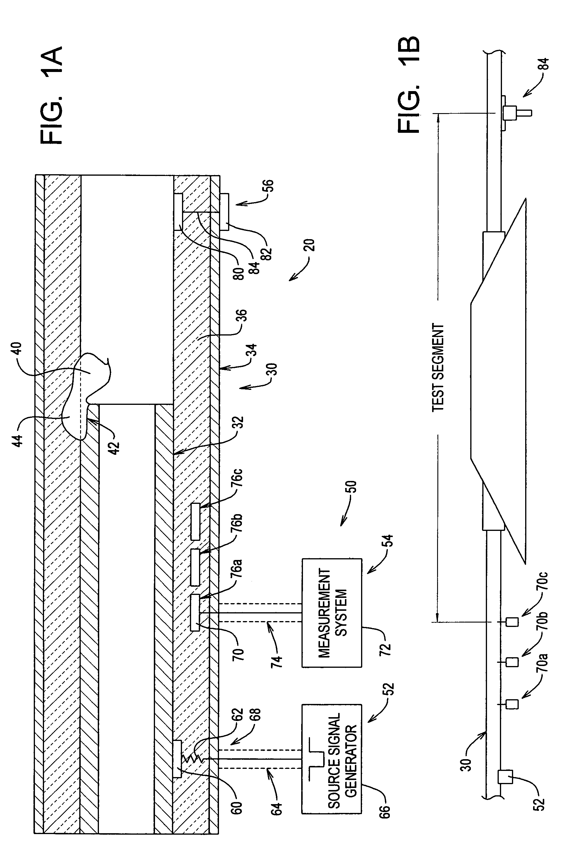
[0018]Referring initially to FIG. 1 of the drawing, depicted therein is an example measurement setup 20 constructed in accordance with, and embodying, the principles of the present invention. The example measurement system 20 is designed test for anomalies in a pipeline system 30 comprising a conductive pipe 32, a conductive outer shield 34, and insulation 36. The pipe 32 and outer shield 34 are typically metallic, and the insulation 36 is typically urethane foam. The pipe 32 is typically centered in the shield 34 by the insulating layer 36. The pipeline system 30 thus effectively forms a constant impedance coaxial transmission line capable of propagating electromagnetic waves in the transverse electromagnetic (TEM) mode.

[0019]Illustrated at 40 in FIG. 1 is an anomaly such as an area of corrosion on the outside of the pipe 32. The anomaly 40 can affect the wave transmission by the pipeline system 30. In particular, the impedance of a coaxial transmission line is a function of the di...


PUM

PropertyMeasurementUnit
dielectric constantaaaaaaaaaa
distanceaaaaaaaaaa
lengthaaaaaaaaaa

Abstract

A system or method of analyzing a conductive member for the presence an anomaly. A test source signal is applied to a first test location on the elongate conductive member remote from the corrosion to cause the test source signal to travel along the pipe through the anomaly. At least one test return signal caused by the test source signal traveling through the anomaly is detected. The at least one test return signal for characteristics associated with the anomaly. Optionally, a perturbation may be applied to the elongate conductive member to place the conductive member in a perturbed state in which the electromagnetic characteristics of the conductive member at the anomaly are altered. The test source signal is applied to the first test location when the conductive member is in the perturbed stated.

Description

RELATED APPLICATIONS[0001]This application is a continuation-in-part of U.S. patent application Ser. No. 10 / 840,488 filed May 6, 2004 now abandoned, which claims priority of U.S. Provisional Patent Application Services No. 60 / 468,626 filed May 6, 2003, the contents of which are incorporated herein by reference.TECHNICAL FIELD[0002]The present invention relates to testing systems and methods for conductive members and, more specifically, to systems and methods for detecting anomalies such as corrosion at remote locations on insulated, shielded metallic pipes.BACKGROUND OF THE INVENTION[0003]Corrosion of steel pipes can degrade the structural integrity of the pipeline system. In some pipeline systems, the metallic pipe is insulated with a urethane foam covering and protected by an outer metallic shield. In other pipeline systems, the metallic pipe is buried. For insulated, shielded pipes, visual inspection is impossible without physically removing the insulation and outer shield. For ...

Claims


Application Information

Patent Timeline
Patent Type & Authority Patents(United States)
IPC IPC(8): G01R27/08G01N17/02G01N22/02G01R31/11
CPCG01N17/00G01N27/20
Inventor BURNETT, GALEFROST, CHARLES A.
Owner EMGWIP LLC
Learn More