Fastener for variable mounting

a technology for fasteners and variable locations, which is applied in the direction of washers, rod connections, screws, etc., can solve the problems of not always being able to access this side of the processor heat sink, components cannot be locked down in a variable location without great difficulty, and retainers are limited

Inactive Publication Date: 2007-04-03
HEWLETT PACKARD DEV CO LP
View PDF21 Cites 80 Cited by
  • Summary
  • Abstract
  • Description
  • Claims
  • Application Information

AI Technical Summary

Problems solved by technology

When such a side of the component cannot be accessed, such as due to the constraints of parts adjacent to the component being mounted, the component cannot be locked down in a variable location without great difficulty, such as disassembly of other system components.
However, such adjustable mounts are often necessary to accommodate system component mechanical tolerances, such as tolerance stack-up in the assembly caused by the upper and lower limit parts coming together.
However, it may not always be possible to access this side of the processor heat sink to tighten a fastener, such as a screw, extending through the slot into the processor heat sink for tightening.
Accordingly, the retainer is limited to uses in which it is disposed parallel to a surface of the circuit board, which may be problematic, such as in situations where an adjustment axis is desired which is perpendicular to the circuit board surface.
Moreover, access to the mounting components in at least two directions is utilized, one for inserting the circuit board and one for engagement of the mount, which may be problematic in particular situations where access is limited.
Although this configuration provides for tightening the fastener from a same direction as the insertion of the processor in the connector assembly (a direction from which there will presumably be access to facilitate insertion of the processor in the connector assembly), the standoff does not allow for adjustment of the attachment point without removal and replacement of the standoff.

Method used


Image

  • Fastener for variable mounting
  • Fastener for variable mounting
  • Fastener for variable mounting

Examples


Embodiment Construction

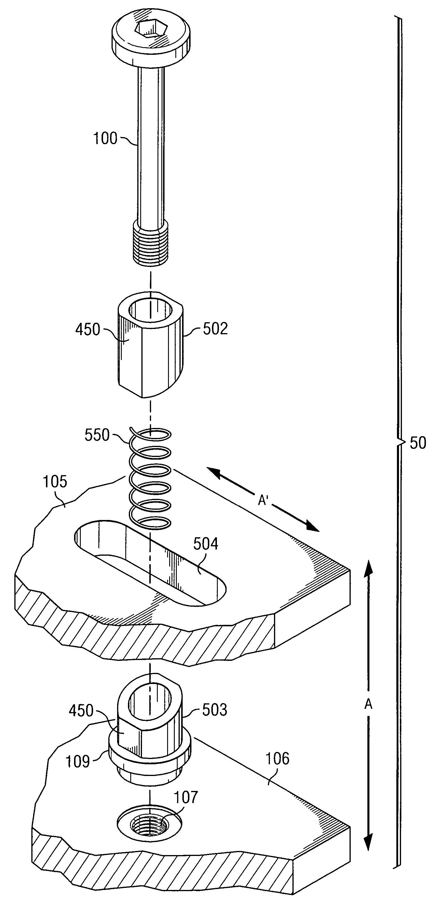
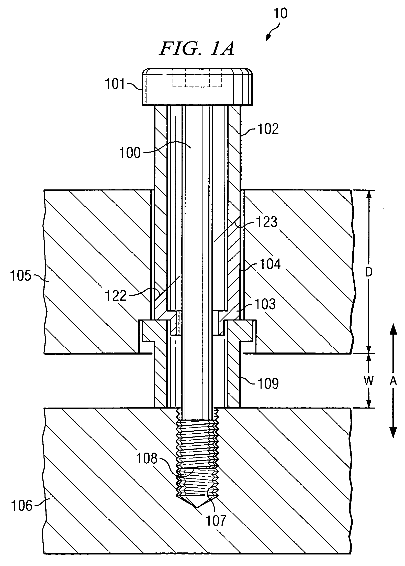
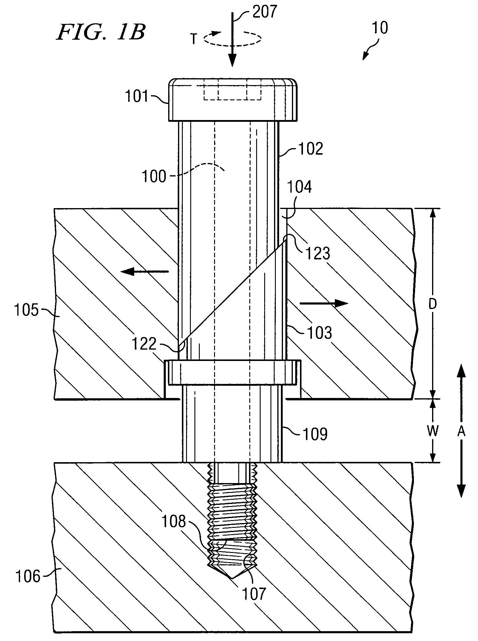
[0017]The present invention is directed to systems and methods providing a fastener assembly for adjustably fastening components, wherein the fastener is engaged by access to the fastener from a direction parallel to an adjustment axis. For example, torque to engage a fastener assembly of an embodiment of the present invention, to lock down a system component in a variable location, may be provided when access to the fastener assembly is only available in the direction of adjustment or movement of the component.

[0018]Embodiments of the present invention utilize wedge portions, as may be drawn together by an adjustment means such as a screw, bolt, rack, etcetera, to exert a retaining force orthogonal to an adjustment axis and the axis associated with fastener assembly engagement access. For example, embodiments of the invention may comprise two wedge portions, having ends cut at an angle, e.g., each at a 45° angle, thereby providing a wedge shaped profile, and a screw passed therethr...


PUM

PropertyMeasurementUnit
angleaaaaaaaaaa
degrees of freedomaaaaaaaaaa
anglesaaaaaaaaaa

Abstract

A fastener assembly comprising a first wedge portion having an angled end, a second wedge portion having an angled end, and a fastener extending through the first wedge portion and the second wedge portion, wherein a portion of the fastener protrudes from one of the first and second wedge portions for interfacing with a component to be mounted, wherein the angled end of the first wedge portion and the angled end of the second wedge portion are interfaced when the fastener is extended through the first wedge portion and the second wedge portion.

Description

CROSS-REFERENCE TO RELATED APPLICATION[0001]The present application is a divisional of co-pending and commonly assigned U.S. patent application Ser. No. 10 / 365,243 entitled “Fastener for Variable Mounting,” filed Feb. 12, 2003, the disclosure of which is incorporated herein by reference.FIELD OF THE INVENTION[0002]The present invention relates in general to mounting fasteners, and in particular to a wedge-lock fastener for variable mounting.DESCRIPTION OF RELATED ART[0003]In the past, when a system component was to be mounted securely to another component, such as a host circuit board, a system housing, or device cage, with a variable mount, such as to allow adjustment along an axis before securing the device, a slotted fastener receiver, such as a slotted bracket, was used. This was done to allow the mounting fastener to slide in the slot as the position of the component was adjusted prior to locking the part in the desired position. Such a slot is elongated in the direction of the...

Claims


Application Information

Patent Timeline
Patent Type & Authority Patents(United States)
IPC IPC(8): B23P11/00F16D1/00F16B5/02F16B13/08F16B43/00
CPCF16B5/02F16B5/0225F16B43/00F16B13/0891Y10T403/7064Y10T29/49963Y10T403/75Y10T403/7067Y10T29/49947Y10T29/4984Y10T403/76Y10T403/7069
Inventor BOUDREAUX, BRENTPETERSON, ERICRUBENSTEIN, BRANDON
Owner HEWLETT PACKARD DEV CO LP
Why Eureka
Try Eureka