Laser guided celestial identification device

a celestial identification and laser guided technology, applied in the field of celestial observation, can solve the problems of difficult to locate a specific object in the sky, requiring alignment and a solid physical mounting, and requiring a large amount of instruments, so as to improve the range, accuracy and utility of the celestial locating device. , the effect of efficient determination of altitud

Active Publication Date: 2007-04-03
NANTONG SCHMIDT OPTO ELECTRICAL TECH CO LTD
View PDF40 Cites 24 Cited by
  • Summary
  • Abstract
  • Description
  • Claims
  • Application Information

AI Technical Summary

Benefits of technology

[0008]Embodiments of the present invention advance the art of celestial object identification and location by using a bright light beam, such as a laser beam as a pointer to the celestial object of interest, allowing a more enjoyable view of the sky, while holding the locating device in a more comfortable position than in previous devices. Further, the laser beam is visible to nearby viewers, and not just to the operator, and does not suffer from parallax errors inherent to prior art optical sighting devices. Additionally, embodiments of the invention offer improvements in the art of sensing Earth's magnetic field and gravitational pull by strategic placement of sensors.
[0009]Embodiments of the invention improve the ease and comfort of locating and identifying celestial objects by using a laser beam that is projected into the sky on an axis coaxial to a reference plane, and acts as a pointer to the object of interest. In another embodiment, the laser beam is controllably aimed in a direction that is not coaxial with the reference plane. The beam can also be used to outline a larger celestial object such as a constellation or to indicate the direction in which to aim the locating device to find a specific object.
[0011]Other embodiments of this invention are directed to procedures to efficiently determine altitude through strategic placement of a gravitational sensor, thus improving the range, accuracy and utility of the celestial locating device.

Problems solved by technology

Countless books and stories describe specific stars, star groupings and other celestial objects but most people find it difficult to locate a specific object in the sky.
These instruments perform well but are relatively heavy, require alignment and a solid physical mounting.
These designs still require sighting of the object of interest through a viewing axis which can obstruct the user's view of the object and require uncomfortable positioning of the viewing device.
Further, requiring that the observation take place along a viewing axis makes such devices unusable by more than one person at a time.

Method used


Image

  • Laser guided celestial identification device
  • Laser guided celestial identification device
  • Laser guided celestial identification device

Examples


Embodiment Construction

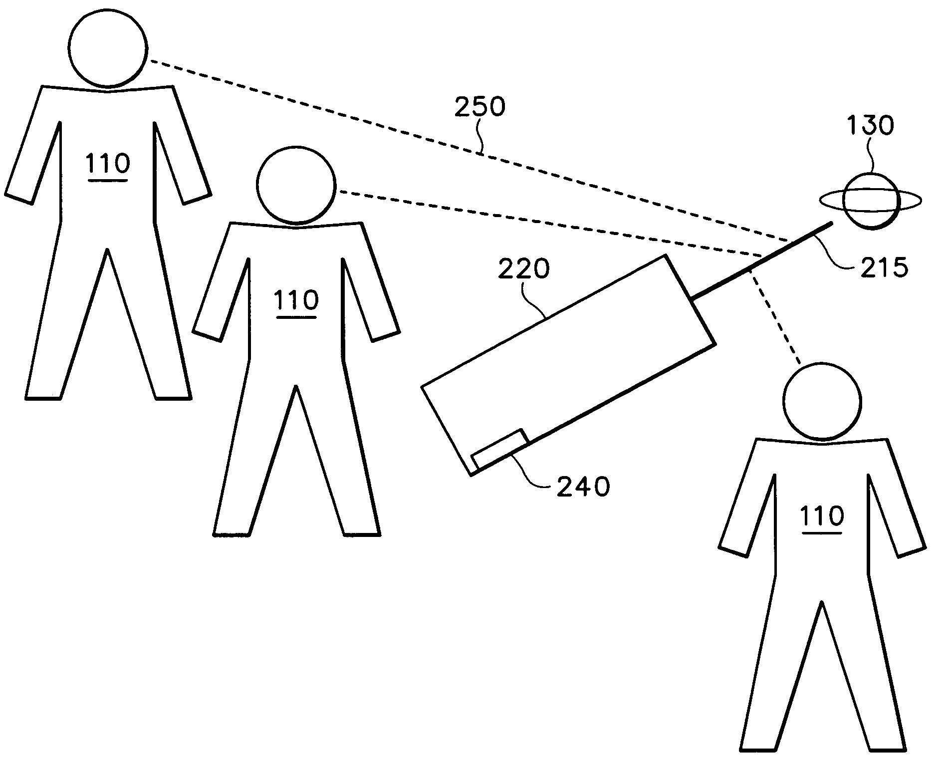
[0012]An object's location in the sky is unambiguously defined by its azimuth and altitude. Azimuth is a measured angle, on a plane approximately parallel with the Earth's surface, between a desired direction and a reference direction such as north. East, for example is an angle +90 degrees away from north, while south is ±180 degrees from north, and west +270 degrees away. North, south, east, and west are all representations of azimuth. Altitude is a measured angle on a plane perpendicular to the Earth's surface. By convention, an altitude of zero degrees points toward the horizon while an azimuth of ninety degrees points directly overhead.

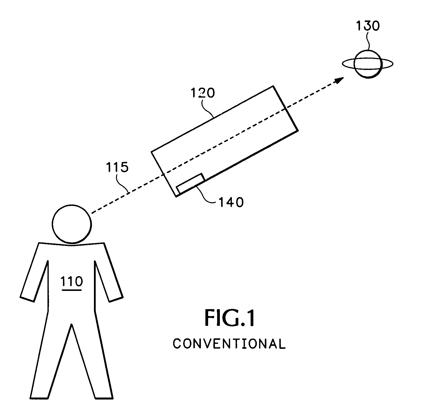
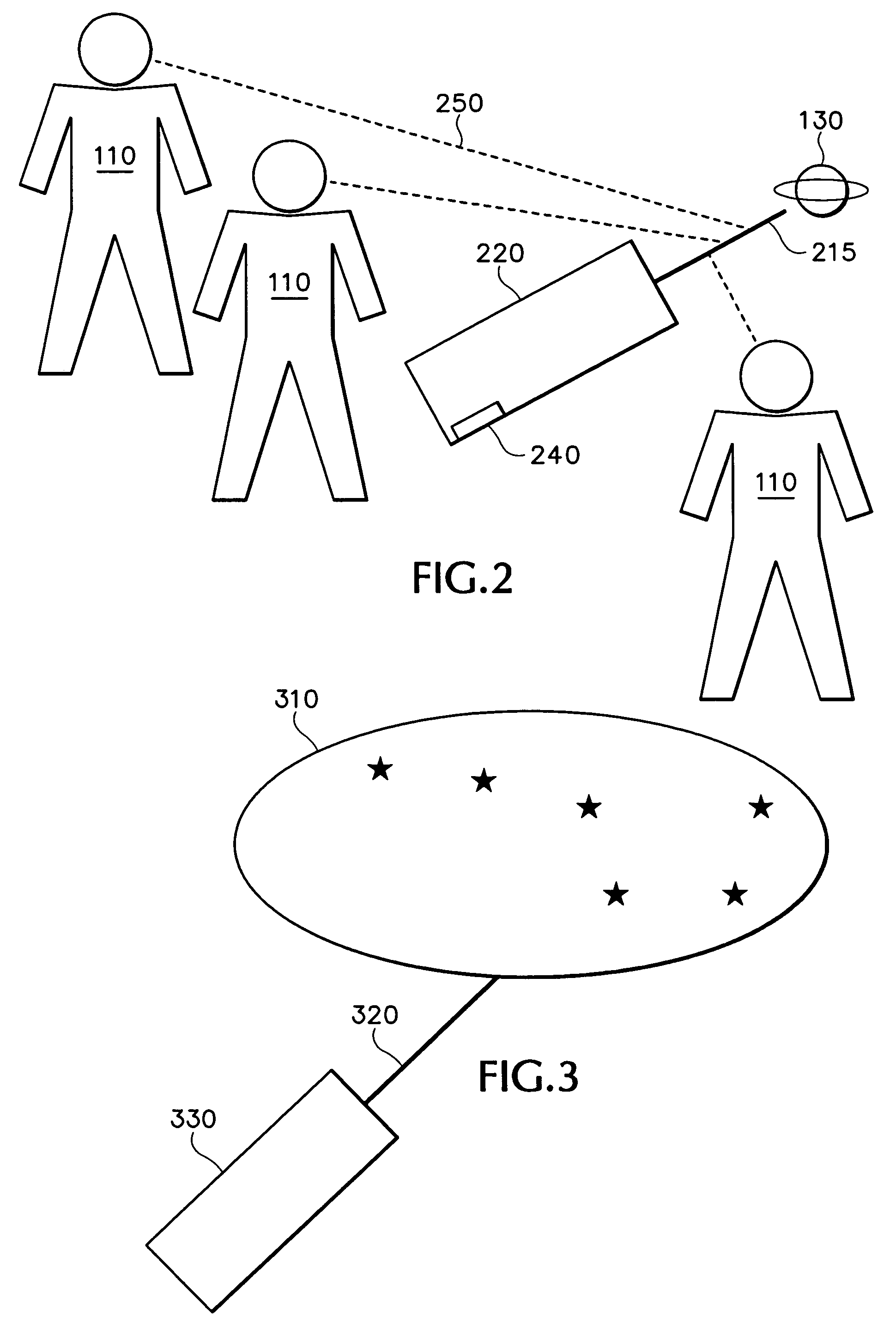
[0013]With reference to FIG. 1, the traditional way to determine an object's coordinates is to construct an aiming device, hereafter referred to as “aimer ”, by equipping an optical viewing device 120 with altitude and azimuth sensors 140 that are aligned with a viewing axis 115 of the viewing device. The viewer 110 sights an object of interest 1...


PUM


Abstract

Disclosed is a celestial identification device. According to some embodiments, the device includes a housing, a positioning sensor, and a light generator structured to generate an indicator beam that can be pointed at celestial objects. The positioning sensor can include sensors to determine altitude and azimuth of the device. The light generator can be a laser and mounted to a moveable pivot or deflected by mirrors and / or lenses such that the light beam points in a different direction than the housing. The device can be coupled to a feedback device, such as an audio player to communicate information about celestial objects to a user. The device can also contain or be coupled to a database of celestial objects such that, when combined with the positional data of the device, can determine at which object the device is pointing. Further, in some embodiments, a celestial device can be selected from the database, and the device operates to point the indicator beam at the selected object, regardless of in which direction the device is pointing.

Description

CROSS REFERENCE TO RELATED APPLICATIONS[0001]This application claims priority from U.S. provisional application 60 / 568,441, filed on May 4, 2004, the contents of which are expressly incorporated herein by reference.TECHNICAL FIELD[0002]This disclosure relates to devices for celestial observation, and, more particularly, to a device for locating and identifying celestial objects.BACKGROUND OF THE INVENTION[0003]Humans have forever been intrigued by the night sky. Stars and other celestial objects have religious, scientific, emotional and mythical importance to peoples of all cultures. Countless books and stories describe specific stars, star groupings and other celestial objects but most people find it difficult to locate a specific object in the sky. Many devices have been created to help, including two and three dimensional planispheres and other such aids.[0004]Optical instruments such as binoculars and telescopes are often mounted on sturdy platforms and equipped with rotational ...

Claims


Application Information

Patent Timeline
Patent Type & Authority Patents(United States)
IPC IPC(8): G01C17/34G09B27/00G09B27/06
CPCG01C17/34G09B27/00G09B27/06Y10S33/21
Inventor ACRES, JOHN F.
Owner NANTONG SCHMIDT OPTO ELECTRICAL TECH CO LTD
Why Eureka
Try Eureka