Controlled bale ejection mechanism

a baler and ejection mechanism technology, applied in baling, packaging, agriculture tools and machines, etc., can solve the problems of inability to vary, damage the baler, and tedious and time-consuming procedures

Active Publication Date: 2007-04-03
DEERE & CO
View PDF7 Cites 26 Cited by
  • Summary
  • Abstract
  • Description
  • Claims
  • Application Information

AI Technical Summary

Benefits of technology

[0007]In view of the foregoing it is an object of the invention to provide a cylindrical baler with an ejection mechanism which will move a discharged bale, in a controlled manner, sufficiently rearwardly behind the gate of the baler so that the gate may be closed without having to move the baler forwardly after ejecting the bale to close the gate.
[0010]An additional object of the invention is the provision of such an ejection mechanism that eliminates twine unwinding and damage to bale wrapping material due to rolling of the bale after discharge.
[0015]This invention prevents substantial bale rolling by controlling the momentum of the bale and releasing the bale close to the ground. This results in a higher quality bale package due to preservation of the wrapping material. If used with lateral translation of the bale clear from the path of the gate, it allows the operator to eject bales on all terrain (including hillsides) without backing up (a common practice on flat terrain with ramps and pushbars).

Problems solved by technology

This is a tedious and time consuming procedure.
If it is not executed properly, there is a possibility that the gate, when closed, may rest on top of the bale.
This may damage the baler or even cause it to turn over.
Both of these approaches present certain inherent disadvantages.
If the baling operation is taking place in a hilly area, the bale may roll down a hill and could position the bale in a location where it would be difficult to retrieve.
With the foregoing designs, such variation is not possible.
However, such a baler still suffers from certain limitations.
All of these requirements add complexity to the baler.
In addition, if the baler is ejecting a bale on a hill with the baler headed downhill, the bale may not be moved entirely free of the gate due to the tendency of the bale to roll toward the baler.
Such devices still tend to cause excessive rolling of the bale; contributing to instability on hills, unrolling of twine and / or damage to wrapping materials.

Method used


Image

  • Controlled bale ejection mechanism
  • Controlled bale ejection mechanism
  • Controlled bale ejection mechanism

Examples


Embodiment Construction

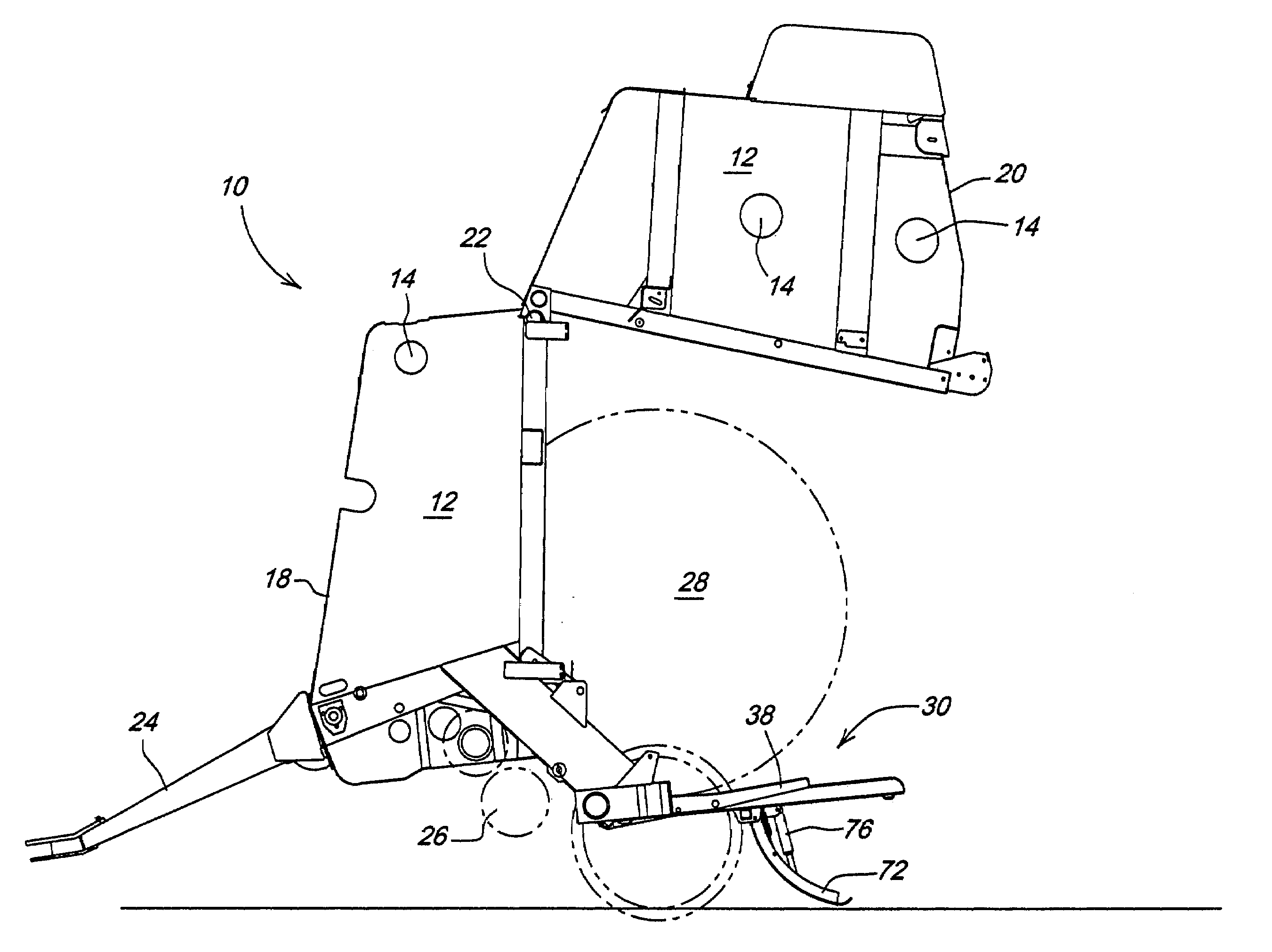
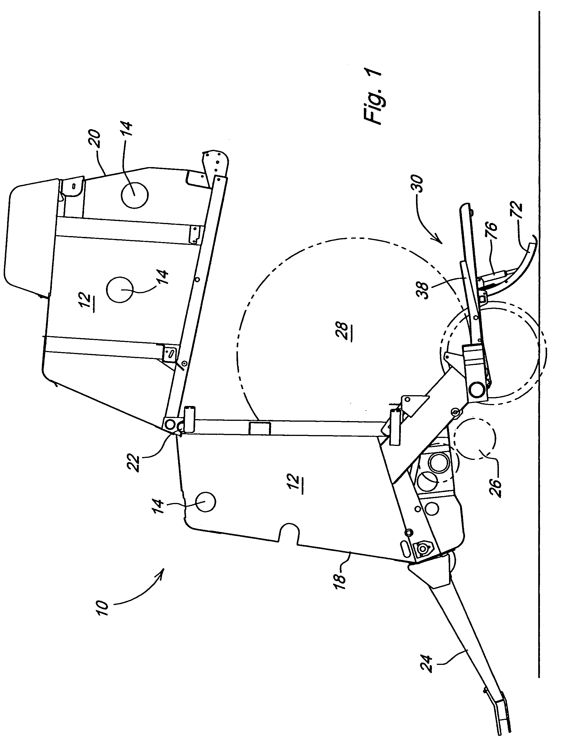
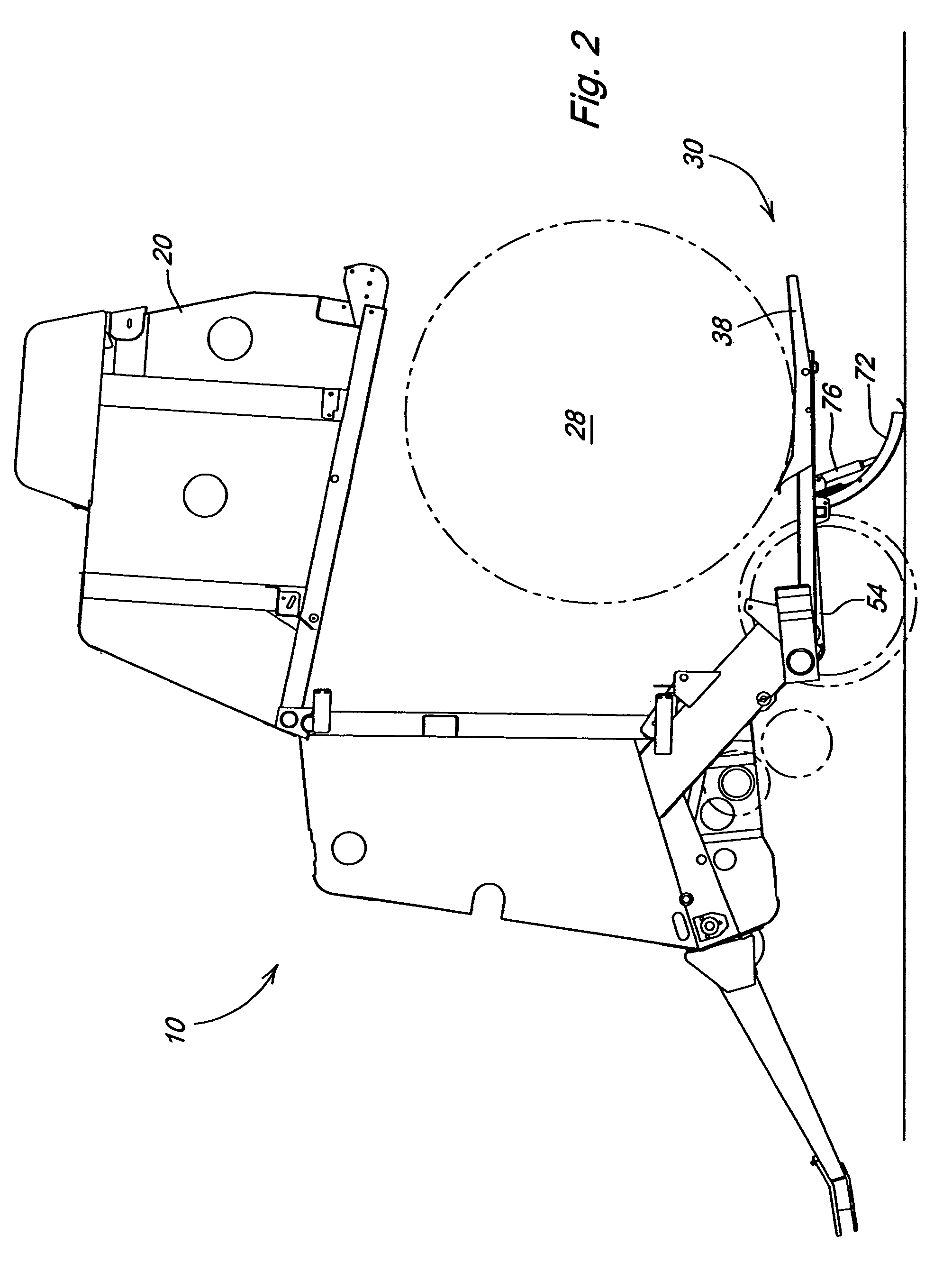
[0027]With reference now to the drawings and particularly FIG. 1, it can be seen that an exemplary agricultural baler for forming cylindrical bales of crop material is designated generally by the numeral 10. Baler 10 is generally comprised of a pair of opposed sidewalls 12, a plurality of longitudinally extending side-by-side belts (not shown) supported on a plurality of rollers 14 (only a few of which are shown). A bale forming chamber is defined by the sidewalls 12, the rollers 14 and belts. The sidewalls 12 (and the components contained therebetween) may be partitioned along a parting line into a front frame section 18 and a bale discharge gate 20 pivotally mounted to front section 18 on a pivot 22. The bale discharge gate 20 is moveable back and forth between a closed position for bale formation and an open position for bale discharge by means of hydraulic cylinders (not shown).

[0028]In the general operation of the baler 10, the baler is drawn through a field by a prime mover (n...


PUM


Abstract

A controlled bale ejection mechanism for an agricultural baler is provided. The mechanism includes a bale support which is positioned below the bale when it is ejected, that catches and supports the bale. The bale support is then translated rearward by a hydraulic cylinder and guided by support rails. As the bale support and bale approach the desired location, the bale support is lowered by tilting the rail assembly downward. An articulating shoe is used to support and lower the rails. The bale support tilts as it is lowered, thereby creating a dumping action. If additional tilting is required due to geometry limitations, additional bale support tilt can be created by a weight shift of the bale support, changing the trajectory of the rail or torque induced by the bale support cylinder. The bale is set down on the ground and the ramp assembly resets to prevent the bale from rolling forward and preparing for the next cycle. Springs are used to retract the articulating shoe and lift the rails into transport position. The timing of this system is integrated into the hydraulic baler functions (primarily the discharge gate) so no additional action is required from the operator when ejecting the bale.

Description

FIELD OF THE INVENTION[0001]The present invention relates generally to balers for forming cylindrical bales (commonly referred to as “round” bales). More particularly, the present invention relates to a cylindrical baler with an ejection mechanism for moving a bale during discharge sufficiently rearward of the baler so that the discharge gate of the baler may be closed without hitting the discharged bale. Specifically, the present invention relates to such an ejection mechanism which places the bale gently on the ground without imparting a rolling motion to the bale thereby preventing roll-away, twine unwrapping and damage to wrapping material.BACKGROUND OF THE INVENTION[0002]Previously known cylindrical balers generally include a rear bale discharge gate pivotally mounted to a front portion of the baler frame. A bale is discharged from such a machine by pivoting the discharge gate rearwardly and upwardly permitting the bale to drop directly onto the ground or by first pivoting the ...

Claims


Application Information

Patent Timeline
Patent Type & Authority Patents(United States)
IPC IPC(8): B30B5/04A01D90/10
CPCA01F15/0833A01F15/0883A01F2015/0891
Inventor DERSCHEID, DANIEL ERIC
Owner DEERE & CO
Why Eureka
Try Eureka