Image display method and apparatus

Inactive Publication Date: 2007-04-03
PANASONIC CORP
View PDF13 Cites 73 Cited by
  • Summary
  • Abstract
  • Description
  • Claims
  • Application Information

AI Technical Summary

Benefits of technology

[0052]According to the above structure, the range of 0≦I<Ir is the most important region to maintain a perceptible contrast. The region in the range of 0≦I<Ir has slope average “r1” rendered greater than the other slope averages. This feature retains good visual quality.
[0053]The range of Ir≦I<I1max covers a bright region. Such a bright region is difficult to perceive degradation in visual quality, even when the bright region has a contrast rendered smaller than a contrast of the region in the range of 0≦I<Ir. Accordingly, the bright region in the range of Ir≦I<I1max has slope average “r2” rendered smaller than slope average

Problems solved by technology

However, the prior art has some problems as discussed below.
Problem 1: When a micro area having great luminance is present in the display screen, then it is difficult to obtain beneficial effects of reducing power consumption.
As a result, the light source tends to be excessively controlled toward bright illumination.
This drawback precludes a reduction in po

Method used


Image

  • Image display method and apparatus
  • Image display method and apparatus
  • Image display method and apparatus

Examples


Embodiment Construction

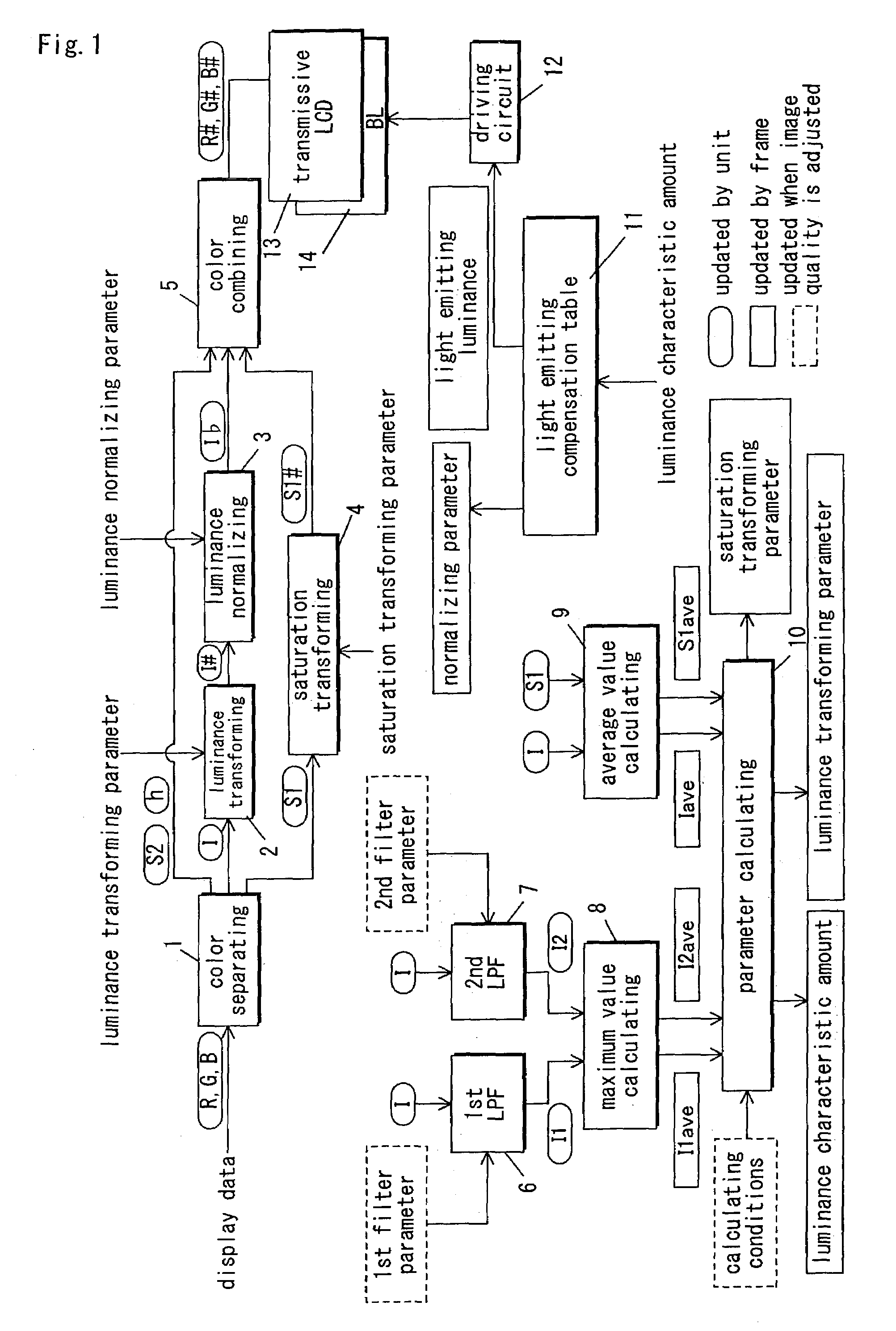
[0089]An embodiment of the present invention will be discussed with reference to the drawings. FIG. 1 is a block diagram illustrating an image display apparatus according to the present embodiment.

[0090]The following discusses how FIG. 1 is referenced, before discussion on components of the image display apparatus. Among values as illustrated in FIG. 1, each round-cornered enclosure contains a value (e.g., luminance “I”) renewed for each pixel of display data. Each solid line, square-cornered enclosure contains a value (e.g., average luminance value “Iave”) renewed for each frame. Each dotted line, square-cornered enclosure contains a value (e.g., calculation condition values) renewed according to display content, display time, and surrounding circumstances when image quality is manually or automatically adjusted.

[0091]In this example of FIG. 1, display data is entered as RGB values into the image display apparatus. RGB values (R#, G#, and B#) in which luminance has been adjusted ar...


PUM


Abstract

There is provided a correlation between adjustment of luminance of a LCD and adjustment of luminance of a backlight. Luminance average value “Iave” is determined from display data. Luminance maximum value “I1max” in a macro area is determined from the display data. Luminance is adjusted with reference to luminance-transformed luminance. In luminance transformation, slope average “r1” in a range of 0≦I<Iave, slope average “r2” in a range of Iave≦I<I1max, and slope average “r3” in a range of I≧I1max establish a relationship of r1≧r2>r3 in an area defined by a horizontal axis showing luminance “I” and a vertical axis showing luminance-transformed luminance “I#”.

Description

BACKGROUND OF THE INVENTION[0001]1. Field of the Invention[0002]The present invention relates to an image display method and apparatus. More particularly, the present invention relates to an art of dynamically adjusting a contrast and light source luminance in accordance with entered display data in an image display apparatus that is operable to irradiate light from a light source such as a backlight onto a light-receiving display device as represented by a liquid crystal panel, in order to provide a high level of perceptible screen luminance.[0003]2. Description of the Related Art[0004]A prior art concerning the above is disclosed in published Japanese Patent Application Laid-Open No. 1-239589. The prior art provides a unit operable to detect a maximum value of an image signal to permit light such as a light source to be irradiated in proportional to the detected maximum value, thereby reducing electric power consumption.[0005]The term “micro area” as set forth herein refers to a s...

Claims


Application Information

Patent Timeline
IPC IPC(8): G09G3/18G09G3/34G09G3/36
CPCG09G3/3406G09G3/3607G09G2320/0285G09G2320/0626G09G2320/0646G09G2330/021G09G2360/16
Inventor IKEDA, JUNOJIMA, SHUICHIHIRASHIMA, TSUYOSHIHATA, RYOUTAKIUCHI, SHINYA
Owner PANASONIC CORP
Why Eureka
Try Eureka