
System and method for determining flow characteristics

Inactive Publication Date: 2007-04-10
KULITE SEMICON PRODS
View PDF8 Cites 17 Cited by
  • Summary
  • Abstract
  • Description
  • Claims
  • Application Information

AI Technical Summary

Benefits of technology

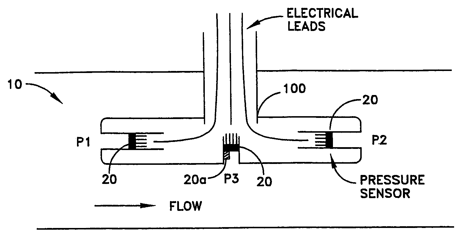
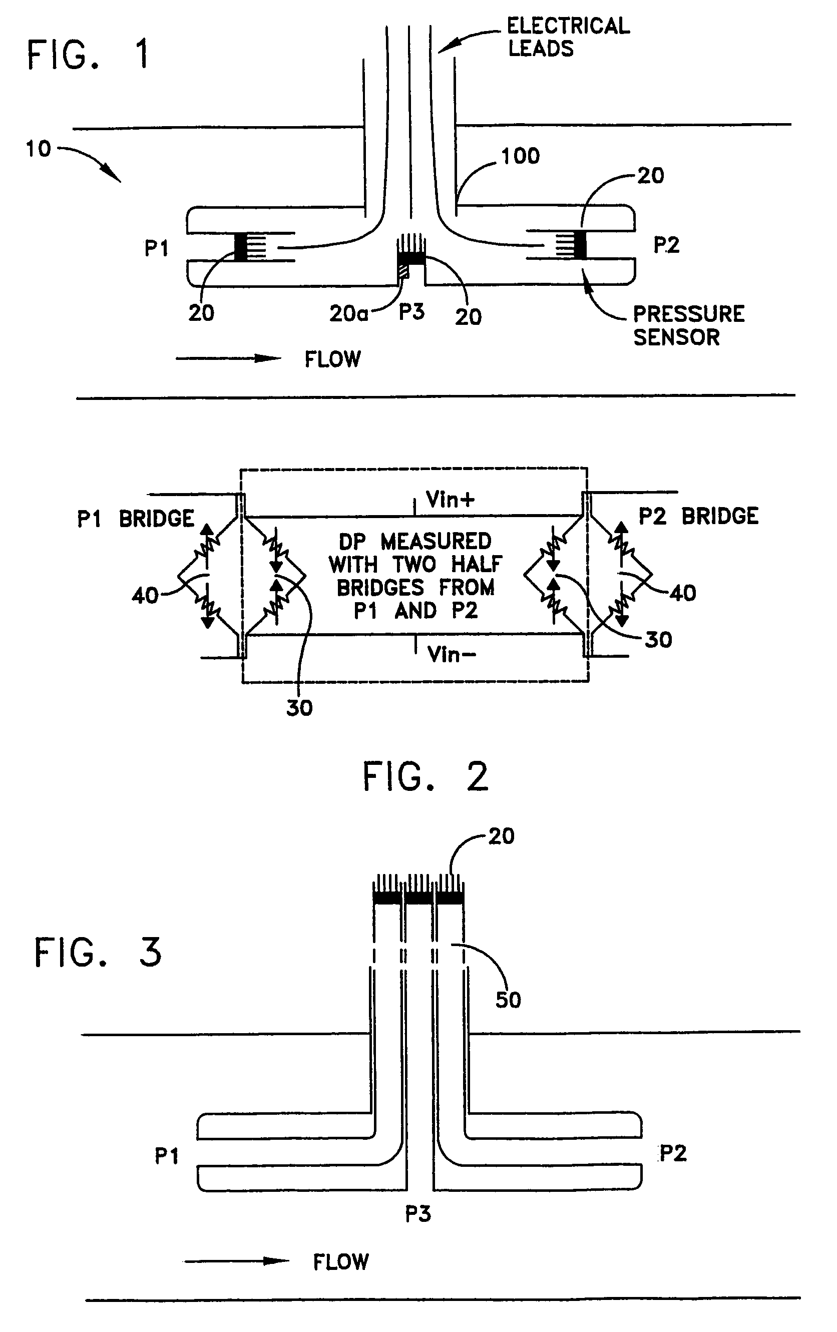
The patent describes a device that measures the pressure of a fluid flow. It has three pressure sensors, a first port for measuring the first pressure, a second port for measuring the second pressure, and a third port for measuring the static pressure. The device also has two outputs that measure the total pressure and the base pressure, and a third output that measures the static pressure. This device helps to accurately measure the pressure of a fluid flow.

Problems solved by technology

This is particularly the case when the flow is unsteady.

Method used


Image

  • System and method for determining flow characteristics
  • System and method for determining flow characteristics
  • System and method for determining flow characteristics

Examples


Embodiment Construction

[0009]It is to be understood that the figures and descriptions of the present invention have been simplified to illustrate elements that are relevant for a clear understanding of the present invention, while eliminating, for the purpose of clarity, many other elements found in typical flow and pressure sensing systems and methods of making and using the same. Those of ordinary skill in the art may recognize that other elements and / or steps are desirable and / or required in implementing the present invention. However, because such elements and steps are well known in the art, and because they do not facilitate a better understanding of the present invention, a discussion of such elements and steps is not provided herein.

[0010]According to an aspect of the present invention there is provided a pressure measurement probe well suited to measure flow direction, as well as flow speed in a steady or unsteady environment. “Flow”, as used herein, refers generally to the act of a fluid moving ...


PUM


Abstract

A fluid flow probe including: first, second and third pressure sensors; a first port for communicating a first pressure to the first pressure sensor; a second port for communicating a second pressure to the second pressure sensor, the second port being substantially oppositely disposed with respect to the first port, a third pressure port suitable for communicating a static pressure to the third pressure sensor; first and second outputs electrically coupled to the first and second pressure sensors, respectively, one of the first and second outputs indicative of a total pressure and the other of the outputs indicative of a base pressure; and, a third output electrically coupled to the third pressure sensor and indicative of the static pressure.

Description

RELATED APPLICATION[0001]This application claims priority of U.S. Patent Application Ser. No. 60 / 611,938, entitled PRESSURE MEASUREMENT PROBE, filed Sep. 22, 2004, the entire disclosure of which is hereby incorporated by reference as if being set forth in its entirety herein.FIELD OF THE INVENTION[0002]The present invention relates to measurement systems and methods for determining flow characteristics.BACKGROUND OF THE INVENTION[0003]In aircraft engines, and other machinery as well, it often occurs that the flow direction of a particular media, such as a fluid like a gas or a liquid, changes or even reverses during device operation. This is particularly the case when the flow is unsteady. It is desirable in certain applications to know the direction and / or the speed of media flow.SUMMARY OF THE INVENTION[0004]A fluid flow probe including: first, second and third pressure sensors; a first port for communicating a first pressure to the first pressure sensor; a second port for communi...

Claims


Application Information

Patent Timeline
Patent Type & Authority Patents(United States)
IPC IPC(8): G01F1/46
CPCG01F1/46
Inventor KURTZ, ANTHONY D.SHANG, TONGHUODEROSA, LOUIS
Owner KULITE SEMICON PRODS
Learn More