Lathe chuck with stepped jaws

a technology of chucks and jaws, applied in the field of universal chucks, can solve the problems of time-consuming and labor-intensive changes, increasing the manufacturing cost of wheels, and adding chucks or chuck components

Inactive Publication Date: 2007-04-17
HAYES LEMMERZ INT
View PDF24 Cites 28 Cited by
  • Summary
  • Abstract
  • Description
  • Claims
  • Application Information

AI Technical Summary

Benefits of technology

[0012]This invention relates to an improved chuck for mounting wheel castings havi

Problems solved by technology

Each of these current approaches clearly has drawbacks in that additional chucks or chuck components must be kept in inventory and time is required to either change out o

Method used


Image

  • Lathe chuck with stepped jaws
  • Lathe chuck with stepped jaws
  • Lathe chuck with stepped jaws

Examples


Embodiment Construction

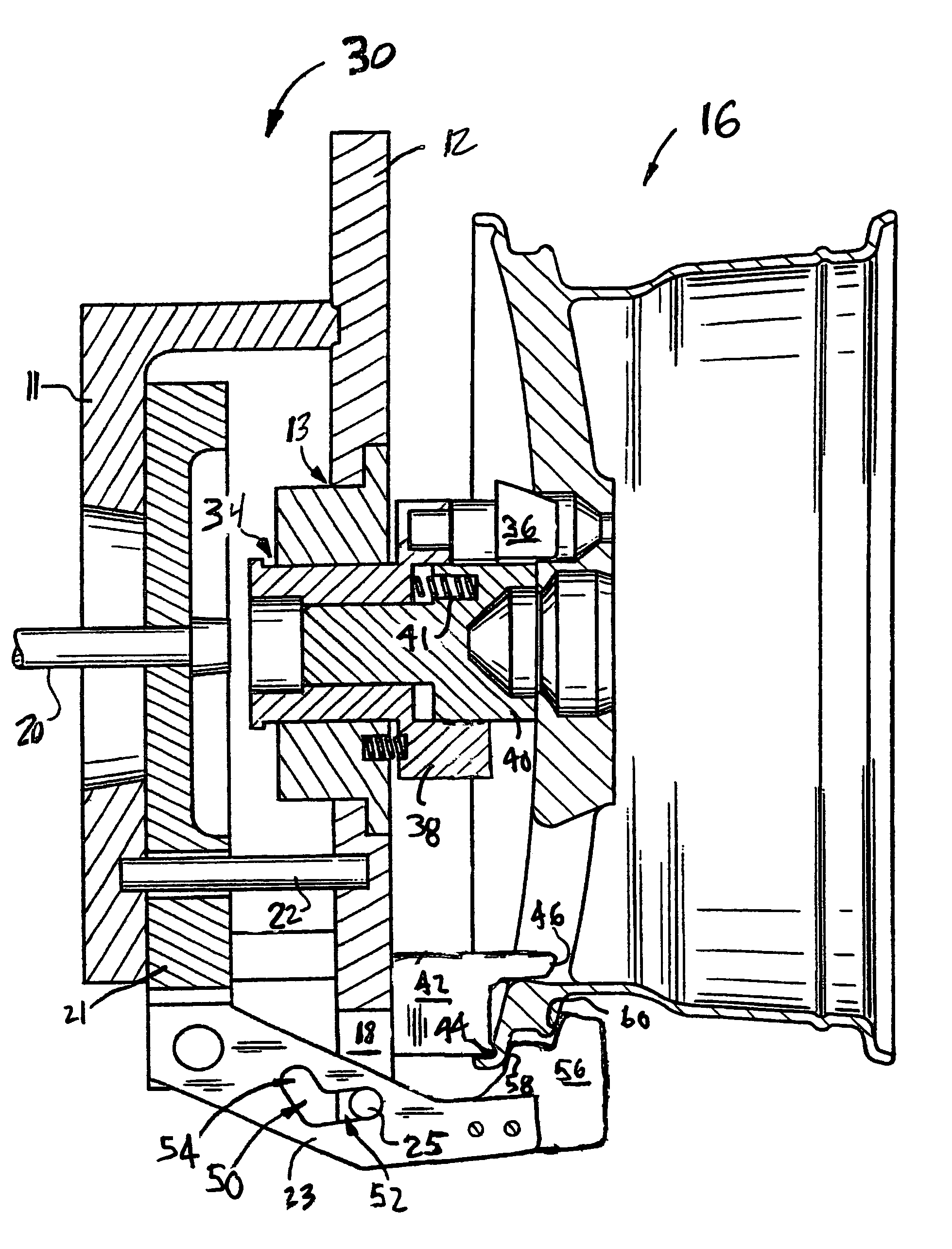
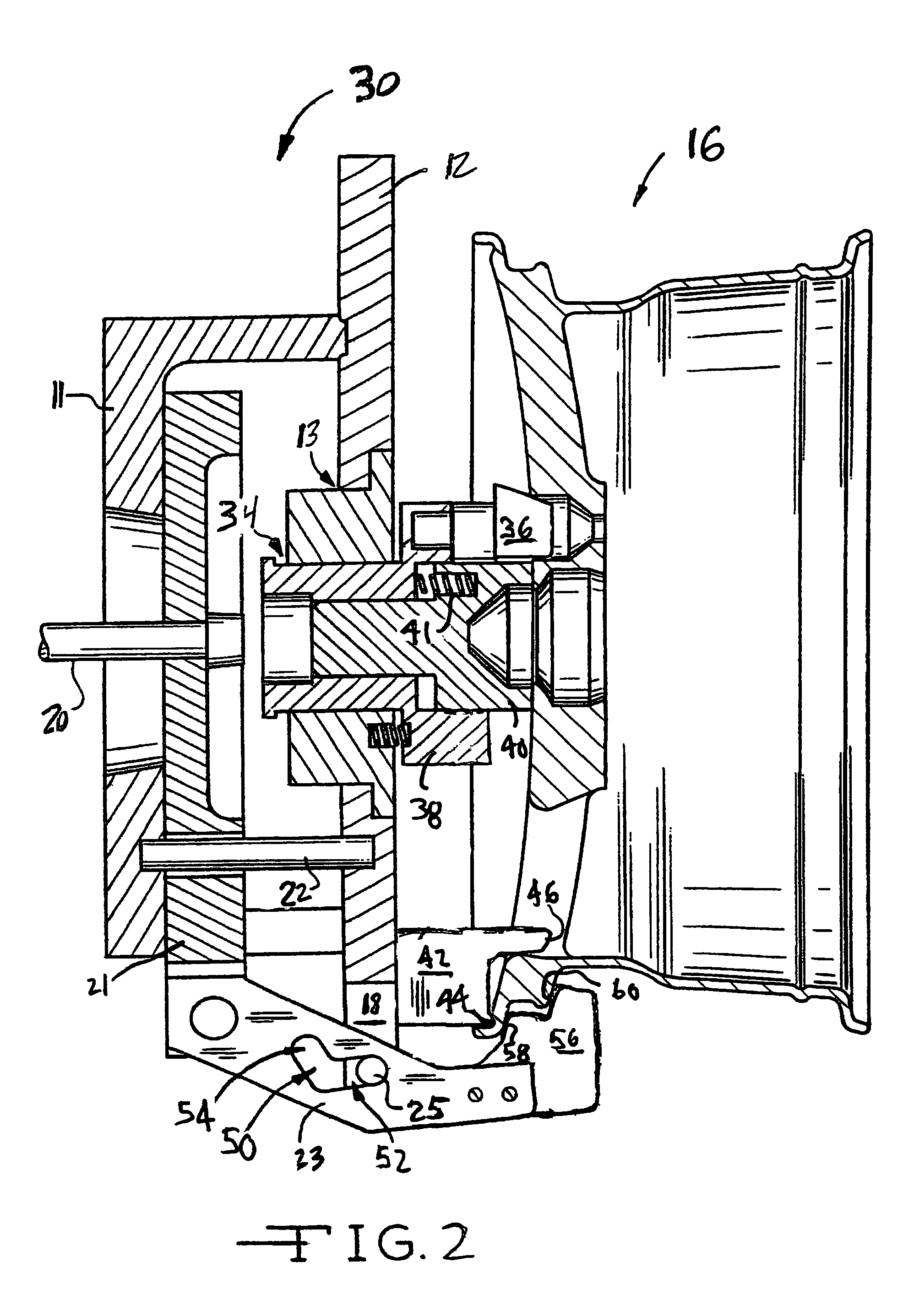
[0019]Referring again to the drawings, there is shown in FIGS. 2 and 3 sectional views of an improved chuck 30 for mounting a vehicle wheel casting upon a wheel lathe (not shown) in accordance with the invention. In the interest of simplicity, not all of the fasteners which secure components of the chuck 30 to one another are shown in FIGS. 2 and 3. The chuck 30 can clamp vehicle wheel castings of varying diameters. In FIG. 2, a one-piece wheel casting 16 of a first diameter is mounted upon the chuck 30. FIG. 3 illustrates a second one-piece wheel casting 32 having a second different diameter, that is less than the first diameter of the wheel 16 shown in FIG. 2, mounted upon the chuck 110.

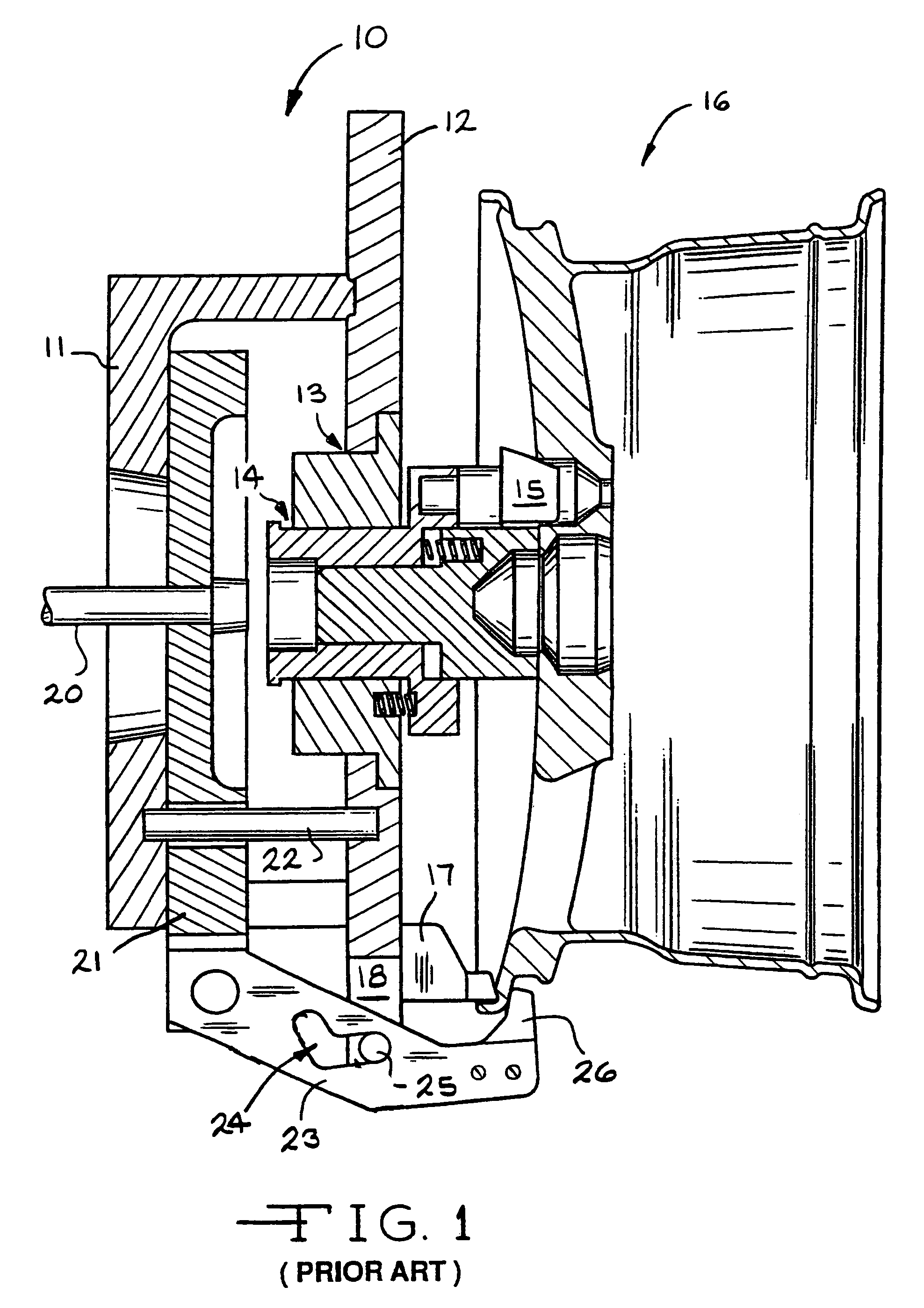
[0020]The improved chuck 30 is similar to the prior art chuck 10 illustrated in FIG. 1 and described above, except as described below. Accordingly, similar reference numbers in FIGS. 2 and 3 refer to similar features and / or elements shown in FIG. 1.

[0021]As described above, the chuck 30 includes a ...


PUM

PropertyMeasurementUnit
Thicknessaaaaaaaaaa
Diameteraaaaaaaaaa
Shapeaaaaaaaaaa

Abstract

A chuck for mounting wheel castings having different diameters upon a wheel lathe for machining the casting to final shape is provided. The chuck includes stepped jaw inserts that cooperate with corresponding stepped part supports to securely mount the wheel castings upon the chuck.

Description

CROSS-REFERENCE TO RELATED APPLICATIONS[0001]Not ApplicableSTATEMENT REGARDING FEDERALLY SPONSORED RESEARCH OR DEVELOPMENT[0002]Not ApplicableREFERENCE TO A SEQUENCE LISTING, A TABLE, OR A COMPUTER PROGRAM LISTING COMPACT DISC APPENDIX[0003]Not ApplicableBACKGROUND OF THE INVENTION[0004]This invention relates in general to fixtures for mounting vehicle wheel castings on machine tools during finishing operations and in particular to a universal chuck for mounting wheel castings having different diameters upon a wheel lathe for machining a final shape.[0005]Light weight alloy vehicle wheels are becoming increasingly popular. Such wheels typically include an annular wheel rim which carries a pneumatic tire. A circular wheel disc is formed across one end of the wheel rim. The wheel disc usually includes a central hub portion supported within the wheel rim by a plurality of wheel spokes. A central pilot hole and plurality of wheel mounting holes are formed through the wheel hub.[0006]One...

Claims


Application Information

Patent Timeline
IPC IPC(8): B23B31/12
CPCB23B5/28B23B31/185B23B31/26Y10T279/3462Y10T279/18Y10T279/1986Y10T279/33
Inventor GATTON, GEOFFREY L.
Owner HAYES LEMMERZ INT
Why Eureka
Try Eureka