Apparatus and method for inserting staple drivers in a cartridge

a technology of staple driver and cartridge, which is applied in the field of devices and methods for inserting staple drivers, can solve the problems of non-adjustable mounting of the guide fixture to the base, and achieve the effect of improving the stability of the guide fixtur

Active Publication Date: 2007-04-24
THE SCNIPKE FAMILY LIMITED LIABILITY
View PDF11 Cites 227 Cited by
  • Summary
  • Abstract
  • Description
  • Claims
  • Application Information

AI Technical Summary

Problems solved by technology

Preferably, the guide fixture is also non-adjustably mounted to the base.

Method used


Image

  • Apparatus and method for inserting staple drivers in a cartridge
  • Apparatus and method for inserting staple drivers in a cartridge
  • Apparatus and method for inserting staple drivers in a cartridge

Examples


Embodiment Construction

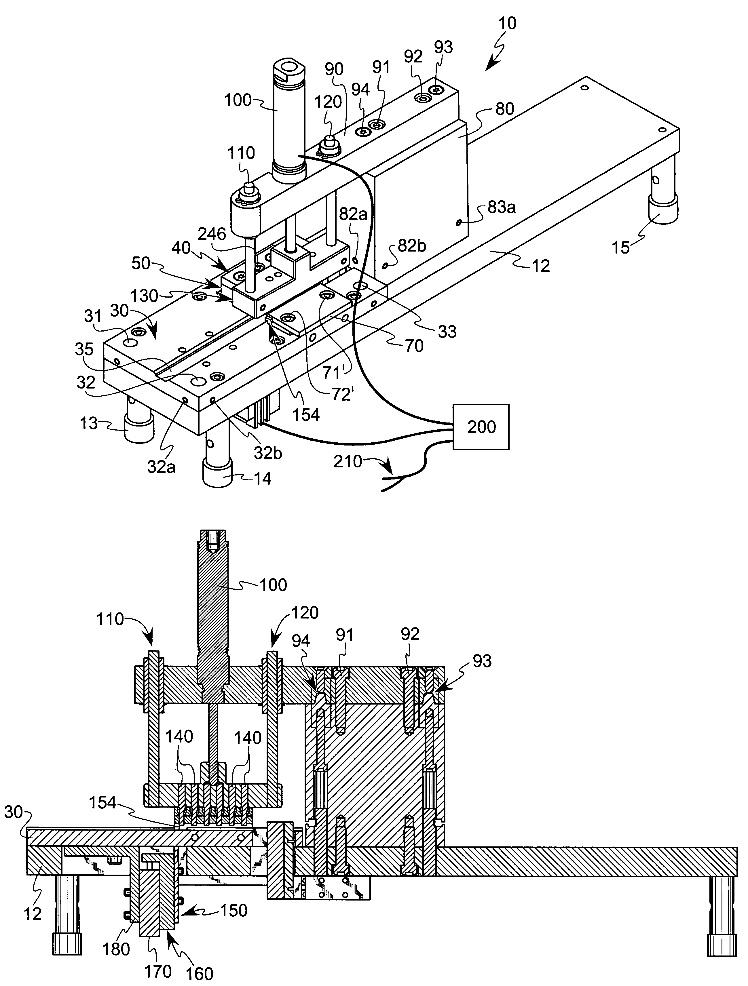
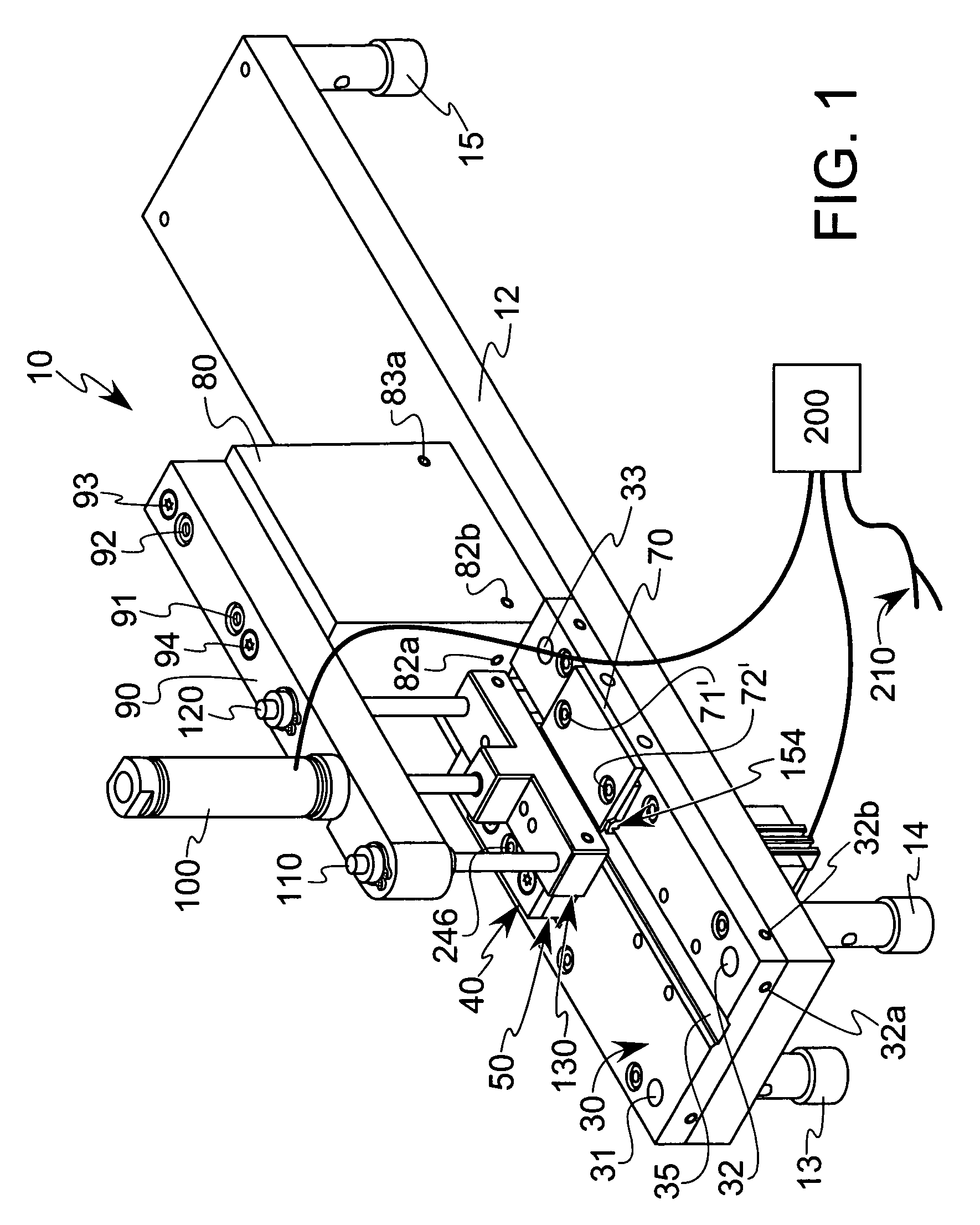
[0041]The preferred staple driver insertion machine 10 is shown in FIG. 1 having a base 12 with four supporting legs 13, 14, 15 and 16 extending downwardly therefrom (leg 16 is not visible in FIG. 1, but is identical to the other legs and is located at the base's fourth corner). The supporting legs 13–16 are not essential, and can be replaced by other suitable support structures. When the machine 10 is in use, the legs are preferably seated at their lower ends against the upwardly facing surface of a table or workbench so that a worker can sit in front of the machine 10 while operating the same as described herein.

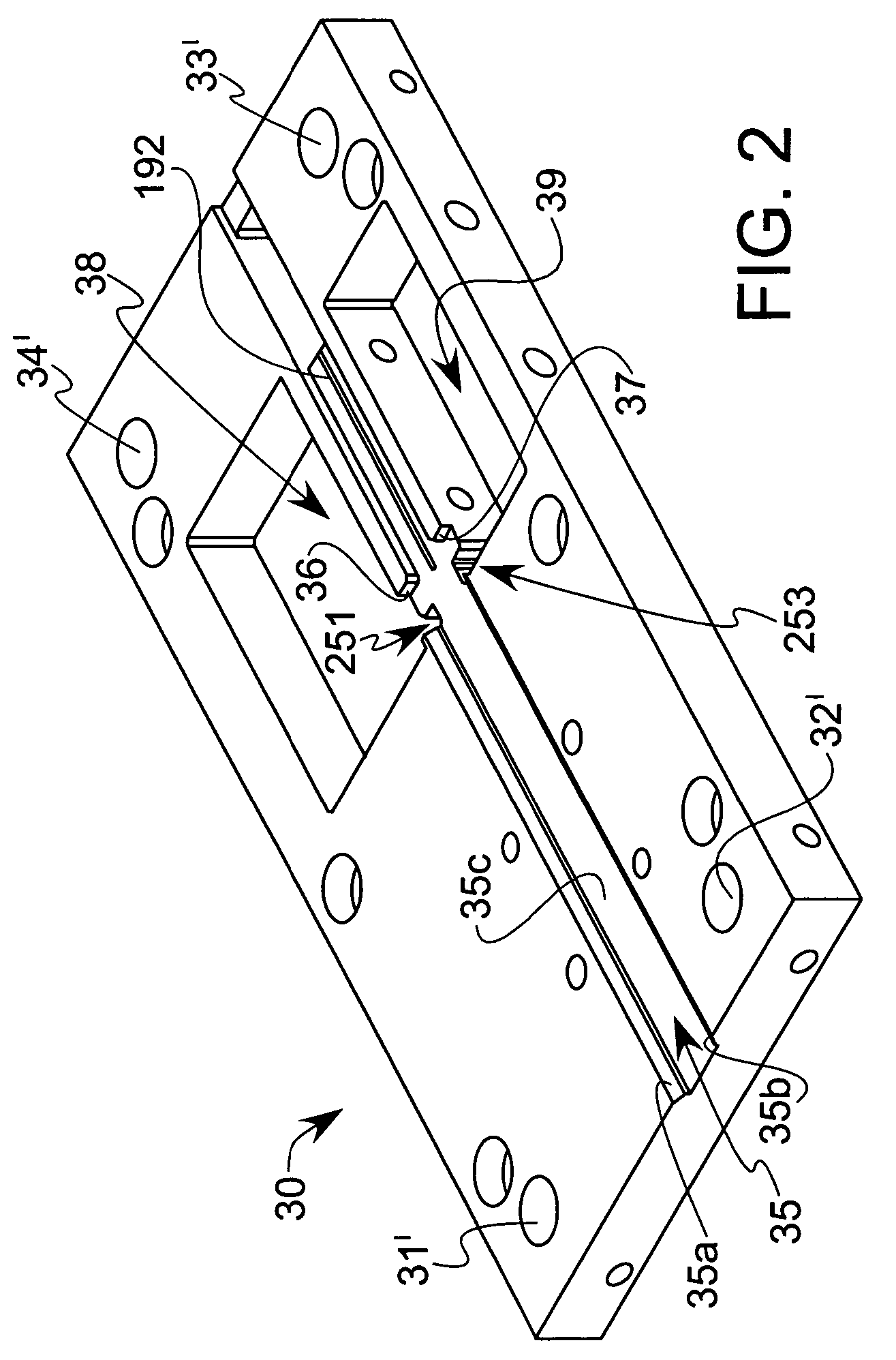
[0042]A cartridge-receiving plate 30 is mounted to the base 12 with means that permit adjustment of the position of the plate 30 relative to the base 12. In the embodiment shown in FIG. 1, there are four dowel pins 31, 32, 33 and 34 (pin 34 is not visible in FIG. 1) that extend loosely through the apertures 31′, 32′, 33′ and 34′ (see FIG. 2) in the corners of the plate 30 ...


PUM

PropertyMeasurementUnit
heightaaaaaaaaaa
sizeaaaaaaaaaa
sizesaaaaaaaaaa

Abstract

An improved method and apparatus for inserting surgical staple drivers into a cartridge, including a base, a cartridge-receiving plate having a channel, upper and lower degating plates having a passage through them, a knife with a sharp edge adjacent the passage and a plunger apparatus that drives the drivers downwardly through the guide passage and into pockets in the cartridge. A cartridge locator plate seats the cartridge against stops in the channel. The cartridge-receiving plate is adjustable relative to the base. The upper and lower degating plates and the knife are not adjustable relative to the base, which avoids the need for re-alignment of the knife and degating plates upon re-mounting on the base. The cartridge-receiving plate is aligned relative to the base. A top riser is adjustably mounted to the base, and a cylinder arm, which holds the plunging apparatus, is non-adjustably mounted to the top riser.

Description

(e) BACKGROUND OF THE INVENTION[0001]1. Field of the Invention[0002]The present invention relates generally to an apparatus and method for inserting discrete articles into cartridges. More particularly, the present invention relates to an improved device and method for inserting staple drivers into surgical stapling cartridges.[0003]2. Description of the Related Art[0004]In the field of microsurgery, a surgical instrument having a cutting blade traverses a specific path through tissue. One feature of the surgical instrument is a single-use cartridge that is a holder for surgical staples. The cartridge is an elongated rectangular plastic body with a longitudinal channel, that serves as a guide for the surgical blade, having rows of small staples on opposite sides of the channel. The staples in the cartridge are aligned parallel to the guide channel. After the blade makes its cut, and other necessary surgical operations are performed, each side of the incision is stapled together to c...

Claims


Application Information

Patent Timeline
Patent Type & Authority Patents(United States)
IPC IPC(8): B29C37/02B23Q3/00B29C65/00
CPCA61B17/07207A61B2017/0688Y10T29/49895Y10T29/53487A61B2017/07271A61B2017/07278
Inventor DOEPKER, BRIAN T.ERHART, DAVID B.SCHNIPKE, RONALD J.
Owner THE SCNIPKE FAMILY LIMITED LIABILITY
Why Eureka
Try Eureka