Bearing arrangement for vibrationally mounting a grinding disk in a grinder

a technology for grinding disks and bearings, which is applied in the direction of portable grinding machines, grinding heads, metal-working equipment, etc., can solve the problems of inability to install plastic bridges with a plurality of vibration legs, limited installation space for vibration legs,

Inactive Publication Date: 2007-04-24
ROBERT BOSCH GMBH
View PDF16 Cites 3 Cited by
  • Summary
  • Abstract
  • Description
  • Claims
  • Application Information

AI Technical Summary

Benefits of technology

[0010]Dividing up the individual vibration legs among a plurality of modules offers the advantage that for mounting in a grinding apparatus, less mounting space is needed, since the modules can each be installed individually.
[0015]Preferably, the individual modules each have one groove and / or one tongue, so that adjacent modules, in the mounted state, form a tongue-and-groove connection. This offers the advantage that the strength of the bearing arrangement of the invention, despite being divided up among a plurality of modules, is similar in quality to conventional bearing arrangements with a plastic bridge for connecting the individual vibration legs.
[0018]To make mounting the grinding disk on a grinding apparatus with the bearing arrangement of the invention easier, the guide body, on its side toward the grinding disk, preferably has a protrusion which positively engages a suitably adapted fastening receptacle in the grinding disk.

Problems solved by technology

In grinding apparatuses with integrated removal of dust by vacuum, however, the installation space for the vibration legs is very limited, so that such plastic bridges with a plurality of vibration legs cannot be installed.

Method used


Image

  • Bearing arrangement for vibrationally mounting a grinding disk in a grinder
  • Bearing arrangement for vibrationally mounting a grinding disk in a grinder
  • Bearing arrangement for vibrationally mounting a grinding disk in a grinder

Examples


Embodiment Construction

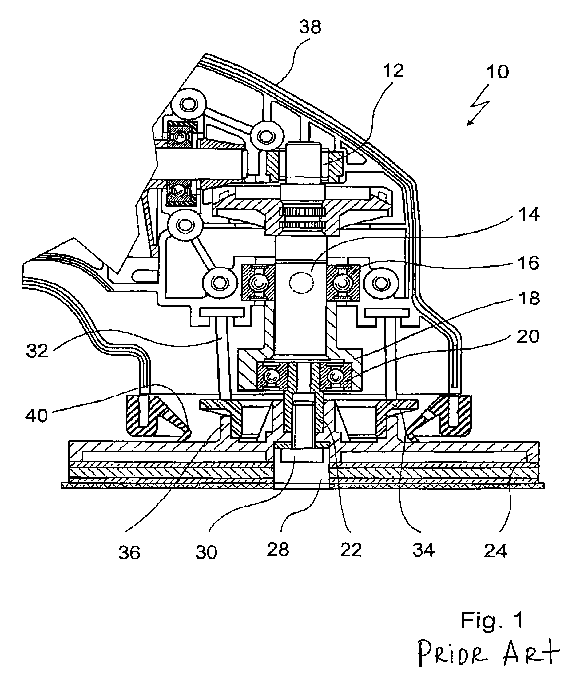
[0029]The cross-sectional view in FIG. 1 shows a vibrating grinder 10, which is of conventional construction and will be described briefly below, in order then to address the special features of the invention.

[0030]The vibrating grinder 10 has an electric motor, which drives a power takeoff shaft 14; the power takeoff shaft 14 is additionally rotatably supported in a ball bearing 16.

[0031]The power takeoff shaft 14 has a free end onto which an eccentric sleeve 18 is press-fitted, so that the eccentric sleeve 18 is secured on the power takeoff shaft 14 in a manner fixed against relative rotation and fixed in the axial direction. Instead of the press fit employed here, however, the fastening of the eccentric sleeve 18 to the power takeoff shaft 14 may be done in some other way, such as by means of a screw connection.

[0032]The eccentric sleeve 18 accordingly rotates with the power takeoff shaft 14 and is therefore balanced relative to the power takeoff shaft 14, to avoid vibration in o...


PUM


Abstract

The invention is based on a bearing arrangement for vibratingly supporting a grinding disk (24) on a grinding apparatus (10), in particular in a vibrating grinder, having a plurality of elastic vibration bodies (48), which can be connected on the one hand to the grinding disk (24) and on the other to the grinding apparatus (10). It is proposed that the vibration bodies (48) are disposed, individually or in groups of a plurality of vibration bodies (48) each, in a plurality of modules (42) that are separate from one another.

Description

CROSS-REFERENCE[0001]The invention described and claimed hereinbelow is also described in PCT / DE 03 / 02337, filed Jul. 11, 2003 and DE 102 51 556.5, filed Nov. 6, 2002. This German Patent Application, whose subject matter is incorporated here by reference, provides the basis for a claim of priority of invention under 35 U.S.C. 119 (a)–(d).BACKGROUND OF THE INVENTION[0002]The invention is based on a bearing arrangement for vibratingly supporting a grinding disk on a grinding apparatus, in particular a ¼-blade vibrating grinder.[0003]In conventional vibrating grinders, the grinding disk is driven to execute lateral vibrating motions by an eccentric; the grinding disk is connected to the grinding apparatus by elastic vibration legs.[0004]The vibration legs prevent the rotary motion of the eccentric from being transmitted to the grinding disk, on the one hand, and thus form a means of securing the grinding disk against relative rotation.[0005]On the other hand, the vibration legs absorb ...

Claims


Application Information

Patent Timeline
Patent Type & Authority Patents(United States)
IPC IPC(8): B24B23/04B24B41/047
CPCB24B23/04B24B41/047
Inventor LAMPRECHT, JUSTUSLUTZ, TOBIASCRAMER, CHRISTOPH
Owner ROBERT BOSCH GMBH
Why Eureka
Try Eureka